Chapter 1. Technical description
5
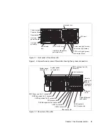
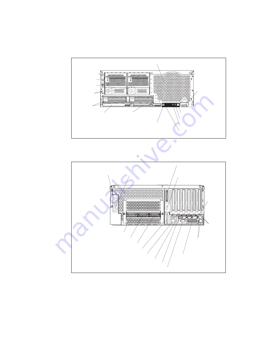
Figure 1-1 Front panel of the xSeries 455
Figure 1-2 shows the rear view of the x455 showing the system connectors.
Figure 1-2 Rear view of the x455
Power button
Reset button
Power-on light
Hot-swap fans
USB port
System-error light (amber)
Information light (amber)
SCSI activity light (green)
Locator light (blue)
DVD/CD-RW drive
Hot swap
power supplies
Blank media
bay
Light Path Diagnostics
panel (pulls out)
Hot swap
drive bays
System power
connector (1)
System power
connector (2)
RXE Expansion Port (B)
connector
Remote
Supervisor
Adapter
connectors
and LEDs
Ethernet
LEDs
Gigabit Ethernet
connectors
RXE Expansion
Port (A) connector
Video connector
USB 2 connector
USB 1 connector
RXE Management Port connector
SCSI connector
Serial connector
SMP Expansion Port 1 connector
SMP Expansion Port 2 connector
SMP Expansion Port 3 connector
Содержание 88553RX
Страница 2: ......
Страница 214: ...200 IBM Eserver xSeries 455 Planning and Installation Guide Figure 5 14 Connect to the x455...
Страница 228: ...214 IBM Eserver xSeries 455 Planning and Installation Guide...
Страница 229: ...IBM Eserver xSeries 455 Planning and Installation Guide...
Страница 230: ......
Страница 231: ......

