Chapter 1. Technical description
27
1.8 Redundancy
The x455 has the following redundancy features to maintain high availability:
Four hot-swap multi-speed fans.
With four hot-swap redundant fans, the x455 has adequate cooling for each of
its major component areas. There are 2 fans located at the front of the server
that direct air through the memory-board assembly and processor-board
assembly. These fans are accessible from the top of the server without having
to open the system panels. In the event of a fan failure, the other fan will
speed up to continue to provide adequate cooling until the fan can be
hot-swapped.
The other two fans are located just behind the power supplies and provide
cooling for the I/O devices. Similar to the SMP Expansion Module fans, these
fans will speed up in the event that one should fail and will compensate for the
reduction in air flow. In general, failed fans should be replaced within 24 hours
following failure.
Due to airflow requirements, fans should not be removed for longer than two
minutes. The fan compartments need to be fully populated even if the fan is
defective. Therefore, remove a defective fan only when a new fan is available
for immediate replacement
Two hot-swap power supplies with separate power cords.
For large configurations, redundancy is achieved only when connected to a
220 V power supply. See 3.5, “Power considerations” on page 87 for details.
To ensure adequate power, a UPS with a rating of RMB 5000 or more is
recommended.
Two hot-swap hard disk drive bays. Using either the onboard LSI chipset or a
ServeRAID adapter, these drives can be configured to form a RAID-1 disk
array for the operating system.
The memory subsystem has a number of redundancy features, including
memory mirroring, as described in “System memory” on page 14.
The layout of the front panel of the x455, showing the location of the four fans,
two drive bays, and two power supplies is shown in Figure 1-1 on page 5.
1.9 Light path diagnostics
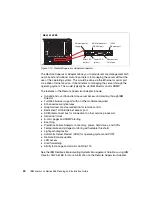
To limit the need to slide the server out of the rack to diagnose problems, a light
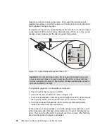
path diagnostics panel has been incorporated in the front of the x455, as shown
in Figure 1-15. This panel can be ejected from the server to view all light path
Содержание 88553RX
Страница 2: ......
Страница 214: ...200 IBM Eserver xSeries 455 Planning and Installation Guide Figure 5 14 Connect to the x455...
Страница 228: ...214 IBM Eserver xSeries 455 Planning and Installation Guide...
Страница 229: ...IBM Eserver xSeries 455 Planning and Installation Guide...
Страница 230: ......
Страница 231: ......

