Chapter 1. Technical description
9
1.4.1 The processor-board assembly
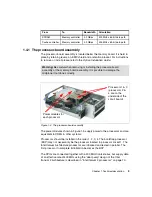
The processor-board assembly is located below the memory board. It is held in
place by retaining levers, an EMC shield and a retention bracket. For instructions
to remove or install please refer to the Option Installation Guide.
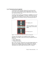
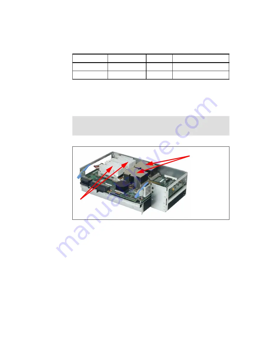
Figure 1-5 The processor-board assembly
The power modules shown in Figure 1-5 supply power to the processors and are
equivalent to VRMs in other systems.
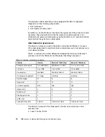
Processors should be installed in the order 1, 2, 3, 4. The bootstrap processor
(BSP) may not necessarily be the processor located in processor socket 1. The
Intel Itanium Architecture processors are initialized and tested in parallel. The
first processor to complete initialization becomes the BSP.
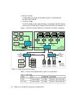
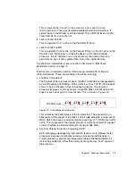
The CPUs are connected together with a 200 MHz frontside bus, but supply data
at an effective rate of 400 MHz using the “dual-pump” design of the Intel
Itanium 2 architecture is described in “Intel Itanium 2 processors” on page 10.
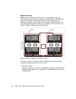
SDRAM
Memory controller
3.2 GBps
400 MHz x 64-bit data path
Cache controller
Memory controller
3.2 GBps
400 MHz x 64-bit data path
From
To
Bandwidth
Calculation
Warning: Be careful when removing or installing the processor-board
assembly or the memory-board assembly. It is possible to damage the
midplane if not done correctly.
Processors 1 & 3
(processors 2 &
4 are on the
underside of the
circuit board)
Power modules for
each processor
Содержание 88553RX
Страница 2: ......
Страница 214: ...200 IBM Eserver xSeries 455 Planning and Installation Guide Figure 5 14 Connect to the x455...
Страница 228: ...214 IBM Eserver xSeries 455 Planning and Installation Guide...
Страница 229: ...IBM Eserver xSeries 455 Planning and Installation Guide...
Страница 230: ......
Страница 231: ......

