2-65
Operation
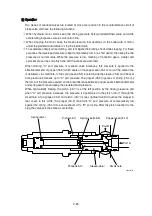
Two pieces of overload valves are located at cross-over position in the counterbalance circuit of
brake valve and have the following functions:
When hydraulic motor starts, keep the driving pressure below predetermined value and while
accelerating, bypasses surplus oil to return line.
When stopping the motor, keep the brake pressure, that develops on the outlet side of motor,
under the predetermined value to stop the inertial force.
To accelerate sharply while starting, and to mitigate the braking shock while stopping. For these
purposes, the developed pressure is kept comparatively low for a short period, then keep the line
pressure as normal value. While the pressure is low, meshing of reduction gears, crawler and
sprocket etc. can be smoothly done and the shock are absorbed.
When starting, "A" port pressure of overload valve increases, this pressure is applied to the
effective diameter of poppet (45-9) which seats on the poppet seat (45-10) and, at the same time,
is delivered, via small hole, to the spring seat (45-5) located inside the sleeve (45-6) and the seat
bore pressure increases up to "A" port pressure. The poppet (45-9) opposes to spring (45-4) by
the force of the pressure exerted on the area difference between poppet seat's effective diameter
and spring seat bore and keep the predetermined pressure.
When hydraulically braking, the piston (45-7) is at the left position by the driving pressure, and
when "A" port pressure increases, the pressure is applied also to the piston (45-7) through the
small hole in the poppet (45-9) and piston (45-7) moves rightward until it touches the stopper in
rear cover. In this while, the poppet (45-9) maintains "A" port pressure at comparatively low
against the spring (45-4) force and exhaust oil to "B" port side. After the piston reached to the
plug, the valve acts the same as at starting.
Port A
Port B
Small hole
Spring(45-4)
Poppet seat(47-10)
Piston(45-7)
Sleeve(45-6)
Poppet(45-9)
Spring seat(45-5)
43092TM08
刮
刯
到
(2)
Содержание HX430L
Страница 11: ...SECTION 1 GENERAL Group 1 Safety Hints 1 1 Group 2 Specifications 1 10 ...
Страница 161: ...4 6 MEMORANDUM HYUNDAI HEAVY INDUSTRIES CO LTD CONSTRUCTION EQUIPMENT DIV ...
Страница 205: ...4 50 No of pin Receptacle connector female Plug connector male 14 1 7 6 14 MG610406 KET SDL CONNECTOR 13 ...
Страница 528: ...8 88 Assemble relief valve assy 45 using torque wrench ÂTightening torque 26Ü2 6 kgfÂm 188Ü18 8 lbfÂft 31 43098TM95 ...
Страница 548: ...8 108 Remove lock nut 22 and then boot 23 14 36078RL14 2507ARL10 ...
Страница 559: ...8 119 14 15 3 Install cover 3 to body 1 and tighten bolts 14 Torque 10 12 5 kgf m 72 3 90 4 lbf ft 7 21078DA10 ...
Страница 589: ...8 149 1 STRUCTURE GROUP 11 WORK EQUIPMENT B SECTION C SECTION B SECTION A C C A B A 21078DA 44 ...


