5-11
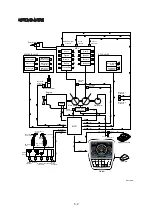
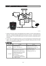
GROUP 8 VARIABLE POWER CONTROL SYSTEM
Main pump Pilot pump
Engine
ECM
Main control valve
Pump power
shift EPPR
MCU
Normal
CN-16
Emergency
CN-16A
CN-16B
Signal
Travel
pressure
Pressure signal
Cluster
Power mode switch signal
CAN #1
Pressure signal
Switch signal
PS
CLUSTER
AIRCON
OFF
CAN #2
Haptic controller
Cluster
Power mode
CAN #2
RH control
lever
LH control
lever
SL
SR
Swing
pressure
AO
AI
Arm in/out
& Bucket in
pressure
BI
Boom up
pressure
BD
PS
PS
PS
PS
Arm in
BU
PS
Boom
down
pressure
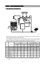
The variable power control system controls the engine and pump mutual power according to RCV
lever stroke and pump load.
It makes fuel saving and smooth control at precise work.
余
The variable power control function can be activated when the power mode is set to all power
mode.
330L5MS10
Description
Working condition
Power mode
P, S, E
Work mode
General (bucket)
Pressure sensor
Normal
侍
Содержание HX430L
Страница 11: ...SECTION 1 GENERAL Group 1 Safety Hints 1 1 Group 2 Specifications 1 10 ...
Страница 161: ...4 6 MEMORANDUM HYUNDAI HEAVY INDUSTRIES CO LTD CONSTRUCTION EQUIPMENT DIV ...
Страница 205: ...4 50 No of pin Receptacle connector female Plug connector male 14 1 7 6 14 MG610406 KET SDL CONNECTOR 13 ...
Страница 528: ...8 88 Assemble relief valve assy 45 using torque wrench ÂTightening torque 26Ü2 6 kgfÂm 188Ü18 8 lbfÂft 31 43098TM95 ...
Страница 548: ...8 108 Remove lock nut 22 and then boot 23 14 36078RL14 2507ARL10 ...
Страница 559: ...8 119 14 15 3 Install cover 3 to body 1 and tighten bolts 14 Torque 10 12 5 kgf m 72 3 90 4 lbf ft 7 21078DA10 ...
Страница 589: ...8 149 1 STRUCTURE GROUP 11 WORK EQUIPMENT B SECTION C SECTION B SECTION A C C A B A 21078DA 44 ...


