8-115
1. REMOVAL AND INSTALL
REMOVAL
Lower the work equipment to the ground
and stop the engine.
Operate the control levers and pedals
several times to release the remaining
pressure in the hydraulic piping.
Loosen the breather slowly to release the
pressure inside the hydraulic tank.
Escaping fluid under pressure can
penetrate the skin causing serious
injury.
When pipes and hoses are disconnected,
the oil inside the piping will flow out, so
catch it in oil pan.
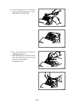
Disconnect all hoses.
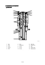
Sling the turning joint assembly (1) and
remove the mounting bolt (2).
Weight : 55 kg (120 lb)
Tightening torque : 12.3
Ü
1.3 kgf · m
(89
Ü
9.4 lbf · ft)
Remove the turning joint assembly.
When removing the turning joint, check
that all the hoses have been disconnected.
8-115
GROUP 8 TURNING JOINT
1
2
1
1)
(1)
(2)
(3)
侍
(4)
(5)
(6)
侍
INSTALL
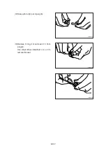
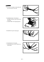
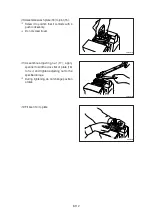
Carry out installation in the reverse order
to removal.
Take care of turning joint direction.
Assemble hoses to their original positions.
Confirm the hydraulic oil level and check
the hydraulic oil leak or not.
2)
(1)
ö
ö
ö
13031GE18
21078DA07
21078DA08
Содержание HX430L
Страница 11: ...SECTION 1 GENERAL Group 1 Safety Hints 1 1 Group 2 Specifications 1 10 ...
Страница 161: ...4 6 MEMORANDUM HYUNDAI HEAVY INDUSTRIES CO LTD CONSTRUCTION EQUIPMENT DIV ...
Страница 205: ...4 50 No of pin Receptacle connector female Plug connector male 14 1 7 6 14 MG610406 KET SDL CONNECTOR 13 ...
Страница 528: ...8 88 Assemble relief valve assy 45 using torque wrench ÂTightening torque 26Ü2 6 kgfÂm 188Ü18 8 lbfÂft 31 43098TM95 ...
Страница 548: ...8 108 Remove lock nut 22 and then boot 23 14 36078RL14 2507ARL10 ...
Страница 559: ...8 119 14 15 3 Install cover 3 to body 1 and tighten bolts 14 Torque 10 12 5 kgf m 72 3 90 4 lbf ft 7 21078DA10 ...
Страница 589: ...8 149 1 STRUCTURE GROUP 11 WORK EQUIPMENT B SECTION C SECTION B SECTION A C C A B A 21078DA 44 ...


