Poseidon2
– Family manual
HW group
www.HW-group.com
81 / 104
Input, Output and Sensor Section
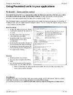
<BinaryInSet>
-
Binary dry contact inputs (next only “Binary input”)
<Entry>
<ID>1</ID>
- Entry identification,
ID (1..64), source for <
CondInputID> for output control, ID in
unique per device, 1..64 are reserved for binary inputs
<Name>Binary 1</Name>
- Defined name of the input (text string, 20 chars)
<Value>0</Value>
- Current value 0/1 (Read only)
<Alarm>0</Alarm>
- alarm settings for this Binary input
– 1 byte 0 = active if on, 1 = active if off, 2 =
inactive
<Delay>0</Delay>
-
0..255 Time delay in seconds to prolong Alarm state reaction. (used for Alarm Start even
for Alarm End reaction)
Similar to Hysteresis but in seconds.
<State>0</State>
- Current sensor state 0 = normal, 1 = Alarm activated but not send (Alarm sending
Email or Trap not activated), 2 = alarm activated
<SNMPTrap>0</SNMPTrap>
- SNMP Trap alarm enable 0 = don't send, 1 = send if value out of SafeRange
<Email>0</Email>
- E-mail alarm enable 0 = don't send, 1 = send if value out of SafeRange
<SMS>0</SMS>
- SMS alarm enable 0 = don't send, 1 = send if value out of SafeRange
<ApDelta>0</ ApDelta>
- AutoPush is a function allowing sending of measured data in case of value
increase/decrease larger than AutoPush delta parameter.
</Entry>
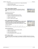
<Entry>
<ID>2</ID>
- Binary input 2
<Name>Binary 2</Name>
<Number>I2</Number>
<Value>0</Value>
<Alarm>2</Alarm>
<Delay>0</Delay>
<State>0</State>
<SNMPTrap>0</SNMPTrap>
<Email>0</Email>
<SMS>0</SMS>
<ApDelta>0</ ApDelta>
</Entry>
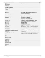
<Entry>
<ID>3</ID>
- Binary input 3
<Name>Binary 3</Name>
<Number>I3</Number>
<Value>0</Value>
<Alarm>2</Alarm>
<Delay>0</Delay>
<State>0</State>
<SNMPTrap>0</SNMPTrap>
<Email>0</Email>
<SMS>0</SMS>
<ApDelta>0</ ApDelta>
</Entry>
</BinaryInSet>
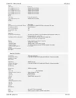
<BinaryOutSet>
- Binary outputs settings & values
<Entry>
<ID>151</ID>
- Entry identification,
ID (151..214), source for <
CondInputID>, ID in unique per
device,
151..200 are reserved for outputs
<Name>RTS</Name>
- Output name (Read only)
<Type>1</Type>
- Type of the binary outputs
0: X/Y = “On” / “Off” (Relay output),
1: X/Y = “On (+10V)” / “Off (-10V)” (RTS output)
2: X/Y = “On (+10V)” / “Off (0V)” (DTR output)
<Mode>0</Mode>
Output control mode (Manual / Local + condition)
0 = Manual output control (value defined by Value tag)
1 = Local output control (On if any alarm)
2 = Local output control (On if value equal to Trigger)
3 = Local output control (On if value higher than Trigger)
4 = Local output control (On if value lower than Trigger)
5 = Local output control (On if Alarm on)
<Value>0</Value>
- 0/1 Current output value
0 = Y (“Off” / “Off (-10V)” / “Off (0V)”)
1 = X (“On” / “On (+10V)” / “On (+10V)”)
R/W for the „Manual output control”
R f
or the „Local output control” (On if any alarm)
<CondInputID>74</CondInputID>
- Condition related input ID
– Poseidon 3268 future
<Trigger>-18.5</Trigger >
- Trigger value for condition
– Poseidon 3268 future
</Entry>

