Poseidon2
– Family manual
HW group
www.HW-group.com
32 / 104
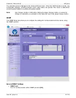
Connection example via RS-485
The bus leads via a 4-wire connection from a Poseidon 1250 unit to two daisy-chained sensors,
Temp-485
and
HTemp-485
. Two twisted pairs are used for the connection.
An
S-Hub
unit is daisy-chained via the RJ45 jack to the second
HTemp-485
sensor using a 4-wire
connection. The brown pair carries power, the blue pair is used for data.
Temp-485
and
HTemp-485
sensors are connected to S-Hub connectors 1 through 3 using 6-wire
connections (brown pair for power, blue pair leads the bus to the device, green pair back from the
device).
Connector 4 of the first
S-Hub
unit is used to connect a
Spider
converter with a patch cable. The
Spider is used to connect three
Temp-1Wire 10m
sensors and one contact (door contact connects to
the blue RJ45 pair).
The second
S-Hub
unit is connected with a patch cable to the
Spider
output.
Temp-485
and
HTemp-485
sensors are connected to S-Hub connectors 1 through 3 using 6-wire
connections (brown pair for power, blue pair leads the bus to the device, green pair back from the
device).
Connector 4 connects a
Temp-485
sensor over a 4-wire connection (brown pair to power the sensor,
blue pair for the A/B signals of the bus).
Termination is enabled at the Temp-485 sensor using the "TERM" jumper.
°C %RH
°C
°C
°C %RH
°C
°C
°C %RH
°C
°C
RJ45
4 pins
RJ45 Patch Straight Cable
4 pins, LAST (Terminated)
1
2
3
4
Spider
10m
°C
10m
°C
10m
°C
Cat5 TP cable, 3 pairs used
RJ12
2 wires cable
Cat5 TP cable, 2 pairs used
Telephone cable, 2/3 wires used
RJ45, MIDDLE cable
RJ45, LAST cable
Term=ON
Mode=MIDDLE
Poseidon 1250
Temp-485
HTemp-485
Temp-1Wire
Door Contact
S-Hub
1
2
3
4
IN
OUT
1
2
3
4


