Poseidon2
– Family manual
HW group
www.HW-group.com
27 / 104
RJ45 - RS-485
The RS-485 bus can be used to connect up to 31 sensors over up to
1000m, even in industrial environments. For convenience and ease of
use, TP cables and RJ45 modular jacks are used to wire the RS485
industrial bus.
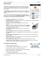
The
RS-485 bus
uses the
blue pair
of wires (pins 4 and 5), labeled A
and B. The
brown pair
(pins 7, 8) is used to supply 12V to
power the
sensors
.
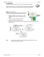
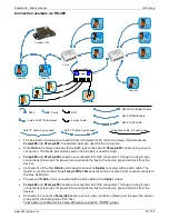
If you use the S-Hub unit and the B-Cable module, the
green pair
of
wires (pins 3, 6) is used for the
return RS-485 connection
. The green
pair of wires is not connected at the Poseidon2 4002 unit.
Maximum wiring length:
Up to 1000m in total
Supported sensors:
temperature, humidity, current, voltage sensors and others (more in
Sensors overview in our product list)
Number of sensors on the RS-485 bus:
Up to 31 physical
sensors
Power:
12V/120 mA, available at the RJ45 jack. Power supplied
by the bus is sufficient for up to 3 external sensors, an
S-Hub
can
be added to power more sensors
Communication cable:
Twisted 2-wire UTP, eventually 4-wire
phone cable
Alarm settings:
Monitoring of the measured values (SafeRange)
Polling period:
800 ms to 10 s (depending on the number of sensors, 10 seconds for 41
sensors)
Sensor address assignment:
Manual, each sensor must have a unique address (see
sensor manual)
Range of sensor IDs:
Sensors use IDs from 48 to 122, the address corresponds to the
ASCII code of 0..9, A..Z, a..z characters.
Disconnected sensor detection:
Yes, discon
nected sensors read as “-999.9”
Alarm if sensor is disconnected:
If the sensor is set to alarm whenever its reading is
outside of the safe range, disconnection triggers the alarm
General RS-485 characteristics
Maximum wiring length 1000 m
Up to 32 devices on the bus (Poseidon unit + 31 sensors)
High resistance to noise in industrial environments
Daisy chain topology is necessary (as opposed to star topology)
Each device must have a unique address
Wire polarity must be respected
Line must be terminated at the beginning and at the end
Port 1
– RJ45
1
-
Not used
2
-
Not used
3
-
485 B return
4
B (-)
RS-485
5
A (+)
6
485 A return
7
GND
Ground
8
+12V
Power

