Poseidon2
– Family manual
HW group
www.HW-group.com
29 / 104
Termination of RS-485 bus
The RS-485 bus must be terminated at its end. The following options are available:
Internal jumper
on certain sensors (jumper named TERM or TERMINATOR)
– for example
Temp-485 or HTemp-485
B-Cable adapter
with “LAST” configuration selected using the switches
By
an external resistor
for sensors that do not have clamp connector or a DIP switch
(Temp-485-Pt100). Terminate the RS-485 with an external resistor at the end of the bus
(connect the resistor between clamps A and B on the last sensor).
Value of this resistor is 120Ω. For short wirings, 470 Ω can be used to reduce the current
consumption of the sensors.
Note:
A disadvantage is that it is necessary to have a wiring topology
with a single
beginning and a single, terminated end
, as opposed to the popular star topology with a single
interconnection point.
Special accessories for the RS-485 bus
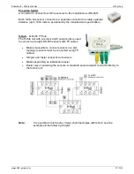
B-Cable
- RJ45 / 4-wire connection
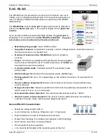
The B-Cable module is an adapter that converts a RJ45 jack
connection to a block of 4 terminals
A,B,+,
–
.
Some of the available RS-485 sensors already have a RJ45
jack; however, some only have 4 terminals labeled
A,B,+,-
.
Such sensors can be connected to the Poseidon 1250 unit or to
an S-Hub using either a TP cable (4 or 6 wires) or the B-Cable
module.
The 4-wire connection
length should not exceed
20 cm.
Sensor position on the RS-
485 bus (MIDDLE / LAST)
is selected with jumpers;
see the picture for details.


