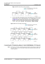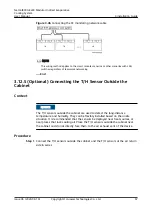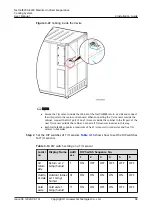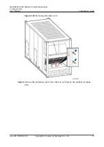
Procedure
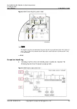
Step 1 Connect one end of the water sensor cable to the water sensor.
Step 2 Route the water sensor cable through the signal cable hole at the bottom of the
electric control box.
Step 3 Connect the other end of the water sensor cable to 1 and 2 on signal terminal
X502.
----End
3.12.4 Teamwork Networking and Monitoring
Signal cables must be routed through protective tubes for protection.
3.12.4.1 Main Control Module
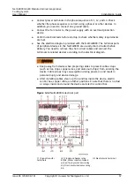
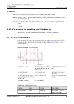
Ports for the teamwork and monitoring network cables are on the main control
module at the rear of the smart cooling product.
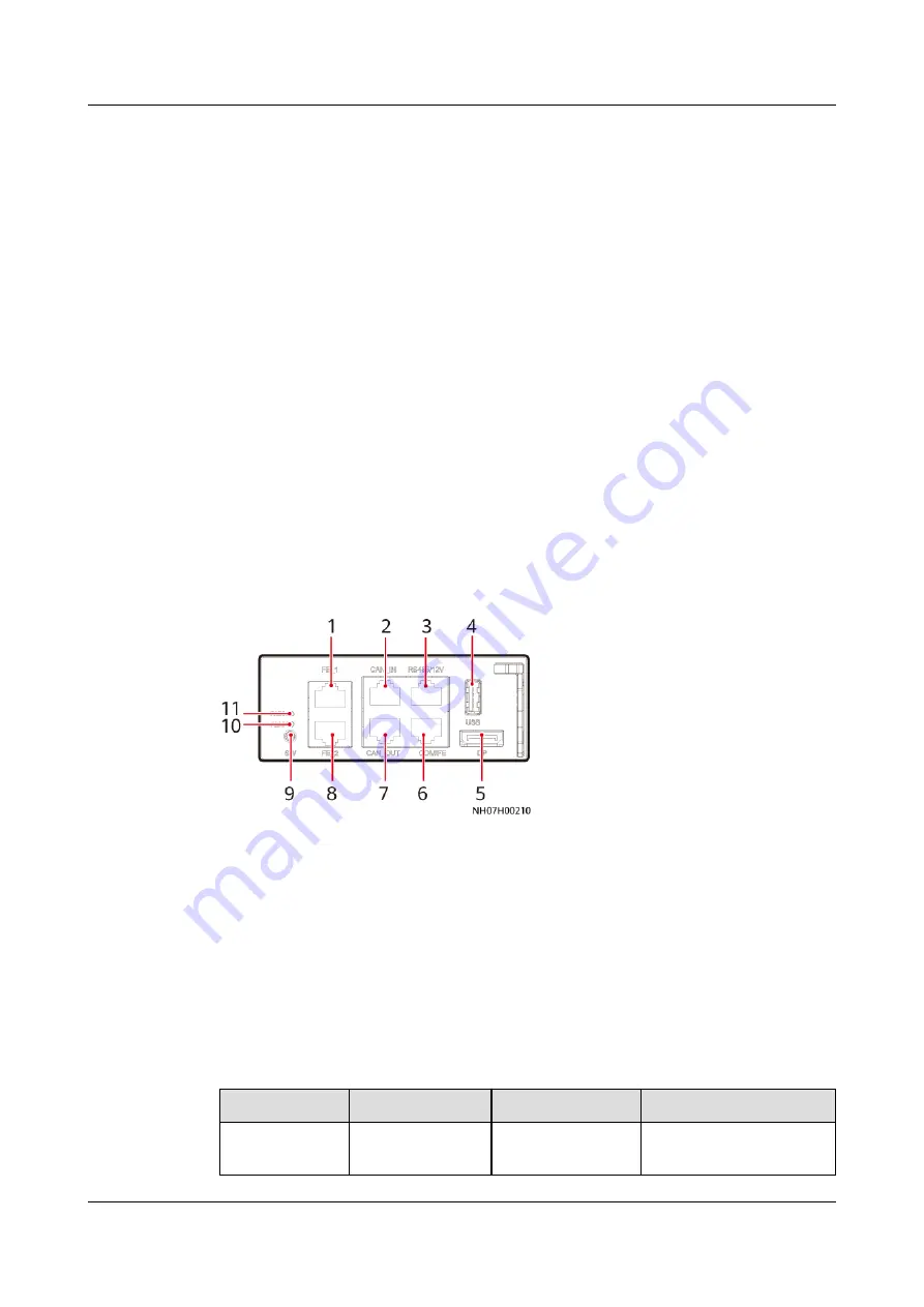
shows a main
control module.
Figure 3-40 Main control module
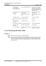
(1) FE_1 (FE terminal)
(2) CAN_IN (input port of the
teamwork CAN/northbound
RS485 port)
(3) RS485/12 V (T/H module
port)
(4) USB (USB port)
(5) DP (display port)
(6) COM/FE (northbound
RS485 port)
(7) CAN_OUT (output port of
the teamwork CAN/northbound
RS485 port)
(8) FE_2 (FE terminal)
(9) SW (for restoring factory
settings)
(10) Alarm indicator
(11) Run indicator
Table 3-12 Indicator description
Name
Color
Status
Description
Run indicator
Green
Blinking
The device is in the
state of startup.
NetCol8000-E220 Modular Indirect Evaporative
Cooling System
User Manual
3 Installation Guide
Issue 06 (2020-08-19)
Copyright © Huawei Technologies Co., Ltd.
63

