background image

3

 Installing Devices

3.1 Layout in the Network Cabinet

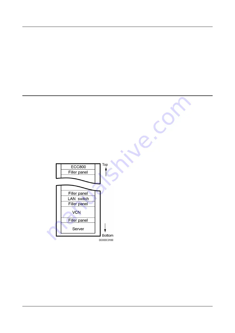
There are multiple types of monitoring components. Make installation plans based

on the configurations. 

Figure 3-1

 shows the installation positions for some

monitoring components for your reference.

Figure 3-1 Device layout in the network cabinet

iMaster NetEco

Device Installation and Commissioning Guide (Data

Center)

3 Installing Devices

Issue 02 (2021-05-12)

Copyright © Huawei Technologies Co., Ltd.

17

Содержание iMaster NetEco V600R021C10

Страница 1: ...iMaster NetEco V600R021C10 Device Installation and Commissioning Guide Data Center Issue 02 Date 2021 05 12 HUAWEI TECHNOLOGIES CO LTD ...

Страница 2: ...cribed in this document may not be within the purchase scope or the usage scope Unless otherwise specified in the contract all statements information and recommendations in this document are provided AS IS without warranties guarantees or representations of any kind either express or implied The information in this document is subject to change without notice Every effort has been made in the prep...

Страница 3: ...oduct Documentation DC V600R021C10_xx Intended Audience This document is intended for Hardware installation engineers Commissioning engineers Maintenance engineers Technical support engineers Symbol Conventions The symbols that may be found in this document are defined as follows Symbol Description Indicates a hazard with a high level of risk which if not avoided will result in death or serious in...

Страница 4: ...rsonal injury equipment damage and environment deterioration Change History Issue Release Date Description 02 2021 05 12 This issue is the second official release Optimized the description of setting iBOX parameters on the iBOX WebUI Optimized and added the content related to the UPS Optimized and added the content related to the chiller station 01 2021 04 15 This issue is the first official relea...

Страница 5: ...8X V5 Server 20 3 3 Installing a LAN Switch 22 3 4 Installing an ECC800 Pro Collector 23 3 5 Installing a Smart U Space Manager 24 3 6 Installing a UIM20A Expansion Module 26 3 7 Installing Sensors 28 3 7 1 Installing Cabinet Temperature Sensors 28 3 7 2 Installing a Hydrogen Sensor 29 3 7 3 Installing the Hydrogen Detection System 30 3 7 4 Installing a Smoke Detector 33 3 7 5 Installing a Tempera...

Страница 6: ...ches S5335 S24P4X 73 4 2 1 2 Introduction to Switches S5735 S24P4X 77 4 2 2 Connecting a Monitoring Cable to the NetEco 80 4 2 3 Connecting the Video Management System Cable 81 4 2 3 1 Connecting a Monitoring Cable to a Camera 81 4 2 3 2 Connecting a Monitoring Cable to the IVS1800 81 4 2 4 Connecting the Smart Cooling Product Monitoring Cable 81 4 2 5 Connecting the UPS Monitoring Cable 84 4 2 5 ...

Страница 7: ... Monitoring Cable to the UPS2000 G Modbus 128 4 3 9 2 Connecting a Monitoring Cable to the UPS5000 A 128 4 3 9 3 Connecting a Monitoring Cable to the UPS5000 E UPS5000 S 129 4 3 10 Connecting the PDC Monitoring Cable 130 4 3 10 1 Connecting the PDU8000 Monitoring Cable 130 4 3 10 2 Connecting a Monitoring Cable to the Monitoring Type PDU2000 32 1PH 20 4 M1 130 4 3 10 3 Connecting a Monitoring Cabl...

Страница 8: ...witch 158 6 4 1 Adding an iBOX Collector 158 6 4 1 1 Setting Parameters on the iBOX WebUI 158 6 4 1 2 Creating an iBOX Collector on the NetEco 163 6 4 1 3 iBOX and iBAT Networking 166 6 4 2 Adding a Video Management System 167 6 4 2 1 Obtaining Video Management System Documents 168 6 4 2 2 Commissioning a C3220 M2121 Camera 168 6 4 2 3 Commissioning the IVS1800 174 6 4 2 3 1 Setting Parameters on ...

Страница 9: ...29 6 5 1 3 Setting the ECC800 Pro System Type 230 6 5 1 4 Setting RS485 Parameters for the ECC800 Pro Collector 231 6 5 1 5 Setting NetEco Parameters 233 6 5 1 6 Creating an ECC800 Pro Collector on the NetEco 234 6 5 1 7 Setting the Transparent Transmission Function for the ECC800 Pro Collector 237 6 5 1 8 Setting Transparent Transmission for the UIM20A Expansion Module on the ECC800 Pro WebUI 239...

Страница 10: ... 269 6 5 7 2 Creating a PDU on the NetEco 270 6 5 8 Adding a Fresh Air Unit 271 6 5 8 1 Creating a Fresh Air Unit on the NetEco 271 6 5 9 Adding an rPDU 272 6 5 9 1 Setting Monitoring Parameters for HPXPDU2000 16 3PH 24 6 M1 272 6 5 9 2 Creating an rPDU on the NetEco 273 7 Device Maintenance 275 7 1 Routine Maintenance 275 7 1 1 Monthly maintenance 275 7 1 1 1 Routine Maintenance for the Collector...

Страница 11: ...Water Sensor and Water Detection Cable 297 7 2 4 6 Replacing a Location type Water Sensor and Water Detection Cable 299 7 2 5 Replacing the Management System 300 7 2 5 1 Replacing an M2121 Camera 300 7 2 5 2 Replacing an IVS1800 301 7 2 5 3 Replacing a Hard Disk for the IVS1800 302 7 2 6 Replacing the Access Management System 305 7 2 6 1 Replacing an Access Controller 305 7 2 6 2 Replacing a Doubl...

Страница 12: ...Follow local laws and regulations when installing operating or maintaining the equipment The safety instructions in this document are only supplements to local laws and regulations Huawei will not be liable for any consequences of the following circumstances Operation beyond the conditions specified in this document Installation or use in environments which are not specified in relevant internatio...

Страница 13: ...lation operation and maintenance Before handling a conductor surface or terminal measure the contact point voltage and ensure that there is no risk of electric shock After installing the equipment remove idle packing materials such as cartons foam plastics and cable ties from the equipment area In the case of a fire immediately leave the building or the equipment area and turn on the fire alarm be...

Страница 14: ...sed during equipment transportation or installation in a timely manner Equipment with scratches cannot be exposed to an outdoor environment for a long period of time Before operations ensure that the equipment is firmly secured to the floor or other solid objects such as a wall or an installation rack Do not use water to clean electrical components inside or outside of a cabinet Do not change the ...

Страница 15: ...fessionals personnel who are trained or experienced in equipment operations and are clear of the sources and degree of various potential hazards in equipment installation operation maintenance Trained personnel personnel who are technically trained have required experience are aware of possible hazards on themselves in certain operations and are able to take protective measures to minimize the haz...

Страница 16: ...acilities must be performed by qualified personnel Cabling When routing cables ensure that a distance of at least 30 mm exists between the cables and heat generating components or areas This prevents damage to the insulation layer of the cables Do not route cables behind the air intake and exhaust vents of the equipment Ensure that cables meet the VW 1 or ZB flame spread rating requirements or hig...

Страница 17: ...ackaging materials before storing or transporting them Figure 1 1 Wearing an ESD wrist strap Neutral Ground Voltage It is recommended that the three phase loads be equalized and the neutral ground voltage be kept at less than 2 V to meet power distribution requirements 1 4 Installation Environment Requirements To prevent fire due to high temperature ensure that the ventilation vents or heat dissip...

Страница 18: ...hts Wear personal protective equipment such as the safety helmet and safety belt or waist rope and fasten it to a solid structure Do not mount it on an insecure moveable object or metal object with sharp edges Make sure that the hooks will not slide off Set a restricted area and eye catching signs for working at heights to warn away irrelevant personnel Carry the operation machinery and tools prop...

Страница 19: ...r fiberglass ladders when you need to perform live working at heights When a step ladder is used ensure that the pull ropes are secured and the ladder is held firm Before using a ladder check that it is intact and confirm its load bearing capacity Do not overload it Ensure that the ladder is securely positioned The recommended angle for a ladder against the floor is 75 degrees as shown in the foll...

Страница 20: ...bles inside Metal shavings from drilling may short circuit boards inside the equipment Obtain the consent from the customer and subcontractor before drilling Wear goggles and protective gloves when drilling holes When drilling holes protect the equipment from shavings After drilling clean up any shavings that have accumulated inside or outside the equipment Moving Heavy Objects DANGER When removin...

Страница 21: ...with good condition for transportation to ensure equipment safety Avoid tilt or jolt during transportation Move a cabinet with caution Any bumping or falling may damage the equipment 1 6 Others Exercise caution when shutting down the smart cooling product Doing so may cause equipment and room overheating which will damage the equipment Exercise caution when powering off the rPDU or PDU2000 Doing s...

Страница 22: ...acking List with the customer after verifying that all required items are delivered Step 6 Store the items properly End Follow up Procedure Put the items to be installed immediately onto an ESD surface such as a polyethylene PE bag or an expandable polyethylene EPE foam Pack the items not to be installed immediately with their original packing materials Put them in a dry and cool environment witho...

Страница 23: ...e 5 m Level Step ladder 2 m Phillips screwdriver Phase sequence meter Flat head screwdriver 2 5 mm Adjustable wrench 6 Socket wrench M4 M6 M8 M12 Hex key Box end wrench M6 M8 M12 Torque wrench 28 mm Solid wrench 12 13 18 Cotton cloth Label iMaster NetEco Device Installation and Commissioning Guide Data Center 2 Installation Preparations Issue 02 2021 05 12 Copyright Huawei Technologies Co Ltd 12 ...

Страница 24: ... PVC insulation tape Needle nose pliers Diagonal pliers RJ45 crimping tool Crimping tool Wire strippers Hydraulic pliers Wire clippers Cable tie Multimeter Electroprobe Brush Claw hammer Vacuum cleaner Hacksaw Handsaw iMaster NetEco Device Installation and Commissioning Guide Data Center 2 Installation Preparations Issue 02 2021 05 12 Copyright Huawei Technologies Co Ltd 13 ...

Страница 25: ...t Table 2 2 Transportation and unpacking tools Manual pallet truck Diesel forklift Hoisting rope bearing capacity 400 kg Lever bearing capacity 400 kg 2 3 Personnel Requirements Only trained and qualified personnel who fully understand basic safety precautions are allowed to install and operate a Smart Module CAUTION Huawei will not be liable for any consequence caused by the violation of this doc...

Страница 26: ...the number of AI DI ports on the ECC800 Pro collector is insufficient collect the device to the UIM20A expansion module 2 5 Installation Process Figure 2 2 shows the process for installing and commissioning the iMaster NetEco devices Recommended installation sequence devices inside the cabinet devices outside the cabinet in room devices You can adjust the installation sequence based on the site re...

Страница 27: ...art for the installation and commissioning of NetEco devices iMaster NetEco Device Installation and Commissioning Guide Data Center 2 Installation Preparations Issue 02 2021 05 12 Copyright Huawei Technologies Co Ltd 16 ...

Страница 28: ...ans based on the configurations Figure 3 1 shows the installation positions for some monitoring components for your reference Figure 3 1 Device layout in the network cabinet iMaster NetEco Device Installation and Commissioning Guide Data Center 3 Installing Devices Issue 02 2021 05 12 Copyright Huawei Technologies Co Ltd 17 ...

Страница 29: ...s shown in Figure 3 2 When there is a special grounding requirement and a cabinet ground bar can be deployed use the ground cable prepared by the customer to connect from the device ground point to the cabinet ground bar If no ground cable is delivered with the device the customer needs to prepare the ground cable Figure 3 2 Connecting a device ground cable 3 2 Installing a Server 3 2 1 Installing...

Страница 30: ...of the guide rail clockwise Figure 3 4 Installing a guide rail Step 3 Install the server 1 Lift the server This task requires at least two people 2 Place the server on the guide rails and slide it into the cabinet See 1 in Figure 3 5 3 When the two mounting ears of the server come into contact with the mounting bars on the cabinet tighten their captive screws to secure the server See 2 in Figure 3...

Страница 31: ...r supplies Connect the two power cables to different PDUs End 3 2 2 Installing a 2288X V5 Server Context Tool Phillips screwdriver Materials 2288X V5 server guide rail rubber plug screw Procedure Step 1 Install guide rails iMaster NetEco Device Installation and Commissioning Guide Data Center 3 Installing Devices Issue 02 2021 05 12 Copyright Huawei Technologies Co Ltd 20 ...

Страница 32: ...he guide rails Insert rubber plugs tightly into the upper mounting holes 3 Optional To enhance the rigidness and seismic proof performance of a server you can install bolts at the rear of flexible guide rails Step 2 Place the server on the guide rails and slide it along the guide rails into the cabinet Step 3 Align the two mounting ears of the server with the mounting bars of the cabinet and tight...

Страница 33: ...based on the network cabinet device layout adjust the guide rails or trays and install floating nuts Step 2 Install the mounting ears delivered with the LAN switch and secure the LAN switch to the mounting bars in the front of the cabinet NOTE This section describes only the installation method The actual product appearance prevails iMaster NetEco Device Installation and Commissioning Guide Data C...

Страница 34: ...rt LAN switch is configured one or two power modules need to be installed for the LAN switch onsite Insert the power module into the power slot of the 24 port LAN switch and tighten the captive screws on the power module panel Figure 3 10 Installing a power module for a 24 port LAN switch 3 4 Installing an ECC800 Pro Collector iMaster NetEco Device Installation and Commissioning Guide Data Center ...

Страница 35: ...g ears Figure 3 11 Installing an ECC800 Pro collector Step 4 Connect the ECC800 Pro collector power cable to the PDU2000 End 3 5 Installing a Smart U Space Manager Context The BOM number of the smart U space manager is 52273314 The BOM number of the U Asset Label is 52273315 The smart U space manager consists of the following components Figure 3 12 Smart U space manager appearance 1 Asset detectio...

Страница 36: ...on point on the asset detection strip facilitating asset management In a standard scenario connect a smart U space manager to the COM6 AIDI_6 port on the UIM20A expansion module In a scenario where one UIM20A expansion module maps to four cabinets connect smart U space managers to the COM1 AIDI_1 COM3 AIDI_3 COM5 AIDI_5 and COM7 AIDI_7 ports on the UIM20A expansion module If the number of IT cabin...

Страница 37: ...box 4 Asset detection strip 42 U detection point End 3 6 Installing a UIM20A Expansion Module Procedure Step 1 Secure a mounting ear to each of the two sides of the UIM20A expansion module using four M4 screws iMaster NetEco Device Installation and Commissioning Guide Data Center 3 Installing Devices Issue 02 2021 05 12 Copyright Huawei Technologies Co Ltd 26 ...

Страница 38: ...llation position The third U space from the top to the bottom at the rear of the cabinet Figure 3 16 Installing floating nuts Step 3 Secure the UIM20A expansion module to the cabinet by tightening the M6 screws on the left and right mounting ears clockwise iMaster NetEco Device Installation and Commissioning Guide Data Center 3 Installing Devices Issue 02 2021 05 12 Copyright Huawei Technologies C...

Страница 39: ...ble Step 3 Connect one end of the extension cable to the temperature sensor on the front door Step 4 Connect the other end of the extension cable and the temperature sensor on the rear door to the T H sensor Step 5 Bind the cables with fasteners NOTE The securing positions of fasteners are for reference only The actual mounting holes on the cabinets prevail The temperature sensor is installed in t...

Страница 40: ...used to detect the hydrogen density indoors It works with the hydrogen detection system The hydrogen detection system is installed on the ceiling of the area to be detected iMaster NetEco Device Installation and Commissioning Guide Data Center 3 Installing Devices Issue 02 2021 05 12 Copyright Huawei Technologies Co Ltd 29 ...

Страница 41: ...tly the device may be burned Figure 3 20 Connecting cables End 3 7 3 Installing the Hydrogen Detection System Context The hydrogen detection system is used to detect the hydrogen density indoors When the hydrogen density exceeds the alarm threshold the system generates alarms The hydrogen detection system is installed on the interior wall of the area to be detected Procedure Step 1 Install four ex...

Страница 42: ...bles to 4 Step 3 Prepare one end of a network cable according to Table 3 1 and connect the cable to 7 DANGER Pay attention to the negative and positive polarities of the power supply If the polarities are connected incorrectly the device may be burned iMaster NetEco Device Installation and Commissioning Guide Data Center 3 Installing Devices Issue 02 2021 05 12 Copyright Huawei Technologies Co Ltd...

Страница 43: ...5 GND and idle ports reserved ports 7 RS485 port Table 3 1 Pin mapping for the RS485 port Pin Signal Function Pin 1 orange white D RS485 Pin 2 orange D RS485 Pin 3 green white 12V 12 input Pin 4 blue NC Pin 5 blue white NC Pin 6 green NC Pin 7 brown white NC Pin 8 brown 12V 12 input End iMaster NetEco Device Installation and Commissioning Guide Data Center 3 Installing Devices Issue 02 2021 05 12 ...

Страница 44: ...the room within the area to be detected Prior to installing the smoke detector properly connect the detector cables to avoid unnecessary rework Procedure Step 1 Take out the smoke detector base and mark mounting holes for the base in the appropriate position Figure 3 23 Mounting holes unit mm Step 2 Drill holes and install expansion tubes Install the smoke detector base to the top of the room iMas...

Страница 45: ...ll an ambient temperature and humidity sensor and connect its cables see shipped documents Connect cables to an ambient temperature and humidity sensor before installation Preparations Tool Phillips screwdriver Materials temperature and humidity sensor temperature and humidity sensor base Document temperature and humidity sensor installation position diagram Procedure Step 1 Remove the front cover...

Страница 46: ...r before installation Preparations Tool Phillips screwdriver Materials temperature and humidity sensor temperature and humidity sensor base Document temperature and humidity sensor installation position diagram Procedure Step 1 Install the T H sensor base at the right column position of the IT cabinet about 1 6 m high above the floor in the aisle and then clamp the T H sensor onto the base Step 2 ...

Страница 47: ... range is 1 63 NOTE The numbers indicate the DIP switch settings of the T H sensors Figure 3 26 DIP switch settings for T H sensors Step 3 Connect the communications cables to the T H sensors Figure 3 27 Cable connections to T H sensors iMaster NetEco Device Installation and Commissioning Guide Data Center 3 Installing Devices Issue 02 2021 05 12 Copyright Huawei Technologies Co Ltd 36 ...

Страница 48: ...Water detector 2 Conversion cable end A connecting to the water detector 3 Conversion cable 4 Conversion cable end B connecting to the water detection cable 5 Water detection cable end A connecting to the conversion cable 6 Water detection cable Procedure Step 1 Install the water detector near the collector and secure it using screws or other methods Step 2 Connect the water detection cable to the...

Страница 49: ...ep 4 Plan the installation position for the fastener of the water detection cable Ensure that the water detection cable placed on the fastener is in good contact with the floor NOTICE Do not contact the water detection cable to metal for this action will cause a false alarm Take protective measures when routing a water detection cable Step 5 Tear off the protection paper on the rear of the fastene...

Страница 50: ...be laid out near air exhaust vents of smart cooling products If unavoidable take measures to prevent condensation Step 6 Place the water detection cable onto the fastener secure the fastener and keep the water detection cable in close contact with the floor Figure 3 33 Securing a water detection cable NOTE If multiple water detection cables need to be connected in series connect the male connector...

Страница 51: ...he control host The installation height must not exceed 1 5 m Ensure that the water detection rope is no higher than the ground Hand write the address in the address blank area Figure 3 34 Installation diagram 1 Latch 2 DIN guide track NOTE Touch grounded devices or pipes to eliminate ESD before taking the location type water sensor module Place it gently Protect it against mechanical impact and c...

Страница 52: ...types to complete cable connection After the cable is connected and the water leakage locator is powered on and initialized if the buzzer keeps buzzing and the alarm location is a stable value that is greater than the total length of the water leakage location cable replace the end cap with the other end cap Table 3 2 RJ45 cable wire sequence of the Tie line Pin Definition Pin 1 orange and white R...

Страница 53: ...e 3 37 Securing a water detection cable End 3 8 Installing the Video Management System 3 8 1 Installing an IVS1800 Context By default the IVS1800 is delivered without disks After the IVS1800 is delivered to the site install hard disks as required and then install the IVS1800 in the cabinet Procedure Step 1 Install hard disks 1 Use a PH2 screwdriver to remove the two black screws on the rear of the...

Страница 54: ...that the fastener of the hard disk tray is on a different side from the hard disk port as shown in the lower left figure Figure 3 40 Installing hard disks 4 Insert the hard disk tray back at 45 degrees with the opening of its locking buckle facing downwards hold the screw in the red framed part to lower the hard disk tray until it is level and fasten the black screws on the left and right sides an...

Страница 55: ...are blocked change the guide rails Huawei provides guide rails that can be adjusted from 500 mm to 800 mm for additional purchase if required for IVS1800 installation Do not attach rubber feet on the IVS1800 to save space during cabinet installation 1 Confirm the installation location of guide rails in the cabinet Install cage nuts two at the front and three at the back on each side to secure the ...

Страница 56: ... figure CAUTION Before installing a guide rail check the F L F R labels on the guide rail to identify whether it is for the left or right and which part is the front or rear F L indicates the front end of the left guide rail and F R indicates the front end of the right guide rail Figure 3 45 Installing a guide rail 3 Install a filler panel for guide rails Fasten the M6 screws to install the filler...

Страница 57: ...tall mounting ears Use a PH2 screwdriver to secure the mounting ears to both sides of the front panel of the device with four screws on each side When the device is near the front door of the cabinet fasten screws in hole groups 1 and 2 when the device is near the rear door fasten screws in hole groups 2 and 3 iMaster NetEco Device Installation and Commissioning Guide Data Center 3 Installing Devi...

Страница 58: ...binet 7 Thread M6 screws prepared by the customer through two slotted holes on each mounting ear Fasten the M6 screws using a Phillips screwdriver to fix the mounting ears on the front mounting bars of the cabinet as shown in the lower right figure Figure 3 49 Securing the device Step 3 Power on the device 1 Turn on the power switch 2 Check the indicators on the front panel of the device for its r...

Страница 59: ...ntext The camera needs to be installed on a control skylight Preparations Tool Phillips screwdriver Materials SD card camera Procedure Step 1 Install an SD card 1 Remove the transparent cover using a Phillips screwdriver Figure 3 50 Removing the transparent cover 2 Gently insert the SD card into the SD card slot iMaster NetEco Device Installation and Commissioning Guide Data Center 3 Installing De...

Страница 60: ...st the surveillance angle and tighten the screws to 0 6 N m NOTICE By default the camera is horizontally installed and the surveillance video is displayed horizontally During the installation adjust the surveillance angle to avoid video image rotation after the installation When adjusting the surveillance angle pay attention to the position of the illuminator to prevent the illuminator from being ...

Страница 61: ... N m Figure 3 54 Installing the transparent cover End 3 8 3 Installing the M2121 Camera Cameras can be installed on different objects based on scenarios This section describes how to install a M2121 camera on the wall Prerequisites A camera and tools for installing it have been prepared A network cable for connecting the camera to the LAN switch has been prepared The LAN switch has been normally p...

Страница 62: ...tform you are advised to disable the video buffering function of the camera to increase the service life of the SD card Do not remove the window protective film before the installation is complete Step 2 Check the diameter of the cable outlet on the wall to ensure that the tails can be routed through the cable outlet Paste the drilling sticker in the camera installation position Ensure that the ce...

Страница 63: ...n the camera base points down and seal the outlet with waterproof sealant Figure 3 58 Installing the M2121 camera NOTE The preceding installation method is to route the pigtail through the wall If the pigtail does not need to be routed through the wall route the pigtail out of the cable outlet on the base and cover it with a corrugated pipe Face the cable outlet with BOTTOM on the camera base down...

Страница 64: ... twisted pair is connected between the access controller and the card reader it is recommended that the distance between them do not exceed 30 m Install double door and quadruple door access controllers by referring to this section Procedure Step 1 Mark the mounting holes using the access controller and marker and drill holes using a hammer drill Step 2 Unlock the access controller with the delive...

Страница 65: ...four screws to install the access controller on the wall Figure 3 61 Installing an access controller End iMaster NetEco Device Installation and Commissioning Guide Data Center 3 Installing Devices Issue 02 2021 05 12 Copyright Huawei Technologies Co Ltd 54 ...

Страница 66: ...igure 3 62 Step 2 Close the door place the cutout template at the midline of the door frame in the door opening direction mark the mounting holes and drill holes as shown in Figure 3 62 Figure 3 62 Mark the installation position 1 Door frame 2 Cutout template 3 Door panel Step 3 Remove the hoisting strip using the delivered hex key NOTE Four hex socket screws need to be removed in this step iMaste...

Страница 67: ...et Figure 3 64 Installing a magnetic lock Step 5 Route the electronic lock cable through the cable hole and secure the electronic lock using a hex key as shown by 2 in Figure 3 64 Step 6 Install the magnet 1 Take out the magnet and knock the positing pins of the magnet into the magnet using a rubber mallet iMaster NetEco Device Installation and Commissioning Guide Data Center 3 Installing Devices ...

Страница 68: ...o a correct position because of its elasticity Figure 3 66 Installing a magnet 1 Rubber pad Step 7 Optional Adjust the magnet 1 If the magnet cannot attract the door properly after power on place a magnetized metal part near the magnet to check whether the magnet provides a proper magnetic force 2 If the magnetic lock and the magnet do not work properly check and troubleshoot the circuit End 3 9 3...

Страница 69: ...utout template near the top of the door frame in the door opening direction mark the mounting holes and drill holes as shown in Figure 3 67 Figure 3 67 Mark the installation position 1 Door frame 2 Cutout template 3 Door panel Step 3 Remove the hoisting strip using the delivered hex key NOTE Two hex socket screws need to be removed in this step Figure 3 68 Removing a hoisting strip iMaster NetEco ...

Страница 70: ...ace of the magnetic lock faces the magnet Figure 3 69 Installing a magnetic lock Step 5 Remove the small cover from the magnetic lock and route the cable out of the cable hole as shown in Figure 3 70 Figure 3 70 Connecting cables iMaster NetEco Device Installation and Commissioning Guide Data Center 3 Installing Devices Issue 02 2021 05 12 Copyright Huawei Technologies Co Ltd 59 ...

Страница 71: ...magnet to the door panel do not over tighten the screws so that the rubber pad is elastic The rubber pad will adjust the magnet to a correct position because of its elasticity Figure 3 72 Installing a magnet 1 Rubber pad Step 8 Optional Adjust the magnet 1 If the magnet cannot attract the door properly after power on place a magnetized metal part near the magnet to check whether the magnet provide...

Страница 72: ...sing a hammer drill Figure 3 73 Marking mounting holes unit mm Step 3 Install the baseplate as shown by 3 in Figure 3 74 Step 4 Route the cable of the fingerprint and card reader with a keypad through the cable hole in the baseplate as shown by 4 in Figure 3 74 NOTE The fingerprint and card reader with a key pad is connected to the access actuator by a network cable Step 5 Check that cables are co...

Страница 73: ...oduct in a place with heavy dust or exposed to sunlight Procedure Step 1 Remove the screws set aside from the fingerprint and card reader and remove the baseplate as shown by 1 in Figure 3 76 Step 2 Mark the mounting holes using a marker and drill holes using a hammer drill Figure 3 75 Marking mounting holes unit mm iMaster NetEco Device Installation and Commissioning Guide Data Center 3 Installin...

Страница 74: ...erprint and card reader End 3 9 6 Installing a Card Reader with a Keypad Context It is recommended that the product be installed 30 300 mm close to the equipment room door and 1 4 1 6 m above the floor Do not install the product in a place with heavy dust or exposed to sunlight Procedure Step 1 Remove the screws set aside from the card reader with a keypad and remove the baseplate as shown by 1 in...

Страница 75: ...e card reader with a keypad is connected to the access actuator by a network cable Step 5 Check that cables are correctly connected Step 6 Secure the card reader with a keypad to the baseplate as shown by 5 and 6 in Figure 3 78 Figure 3 78 Installing a card reader with a keypad End iMaster NetEco Device Installation and Commissioning Guide Data Center 3 Installing Devices Issue 02 2021 05 12 Copyr...

Страница 76: ...e Button Context It is recommended that the button be installed 1 4 1 6 m away from the inner door of the protected area and 1 6 m above the floor The appearance of the emergency door release button is for reference only The actual appearance may vary Procedure Step 1 Remove the emergency door release button Figure 3 79 Removing an emergency door release button 1 Remove screws from the emergency d...

Страница 77: ...n Figure 3 81 Installing an emergency door release button 1 Install the base of the emergency door release button as shown by 1 in Figure 3 81 2 Install the glass panel of the emergency door release button as shown by 2 and 3 in Figure 3 81 3 Tighten screws of the emergency door release button using a Phillips screwdriver as shown by 4 in Figure 3 81 End iMaster NetEco Device Installation and Comm...

Страница 78: ...g a Server 4 1 1 Server Ports 4 1 1 1 Server Ports TaiShan 200 Server The TaiShan 200 server Model 2280 is a next generation data center server developed by Huawei Based on Huawei Kunpeng processors the server features efficient computing high security and reliability and an open ecosystem As the monitoring host of the NetEco management system the server processes and analyzes data Figure 4 1 Port...

Страница 79: ...eth6 GE port Reserved 8 eth7 GE port 9 iBMC remote management port Used for connecting to a PC to manage the TaiShan 200 server Model 2280 10 Server serial port Used for connecting to an SMS modem or for commissioning 11 VGA port Used for connecting to a monitor 12 USB port Used for connecting to an external device 4 1 1 2 Server Ports 2288X V5 Server The 2288X V5 server is a next generation Huawe...

Страница 80: ... provide northbound services Connect eth2 and eth3 which are configured as bond1 by default to provide southbound services Connect eth4 and eth5 which are configured as bond2 by default to provide southbound 2 services 2 eth1 GE port 3 eth2 GE port 4 eth3 GE port 5 eth4 GE port 6 eth5 GE port 7 eth6 GE port Reserved 8 eth7 GE port 9 VGA port Used for connecting to a monitor 10 USB port Used for co...

Страница 81: ...and the other end to the transfer cable Connect the other end of the transfer cable to an idle serial port on the server For details about the serial ports on the server see Server Ports NOTE For details see the user manual delivered with the SMS modem Use the connector convertor delivered with the SMS modem if the connector of the serial cable does not match the serial port on the server Step 5 C...

Страница 82: ... is deactivated Step 6 Install the SMS modem driver To install the SMS modem driver see the specifications delivered with the SMS modem NOTE You need to install the driver only when the installation of the driver is required in the specifications delivered with the SMS modem End 4 1 3 Connecting Cables to the 4G SMS Modem Prerequisites An idle USB port is available on the server Context The follow...

Страница 83: ...er cable 1 Connect one end of the USB cable to the USB 2 0 port on the modem 2 Connect the other end of the power adapter to the universal conversion C1 socket 3 Connect the other end of the universal conversion C1 socket to the rPDU through a transfer cable C13 C14 cable or China standard C13 cable After the power cable is connected turn on the power supply The modem indicator should blink regula...

Страница 84: ...1 1 Introduction to Switches S5335 S24P4X Exterior and interior Figure 4 5 Appearance of the S5335 S24P4X Table 4 5 S5335 S24P4X description No Description 1 Twenty four 10 100 1000 BASE T Ethernet electrical ports iMaster NetEco Device Installation and Commissioning Guide Data Center 4 Connecting Monitoring Cables to Devices Issue 02 2021 05 12 Copyright Huawei Technologies Co Ltd 73 ...

Страница 85: ...6 One PNP button NOTICE Holding down the button for more than 6s restores the factory settings and resets the device Pressing the button resets the device Resetting the device will interrupt services Exercise caution when using this button 7 Ground screw NOTE The screw needs to be used with a ground cable 8 Power module slot 1 NOTE Supported power module 1000 W AC PoE power module PAC1000S56 CB 9 ...

Страница 86: ...maximum distance from the protruding port on the front panel to the module handle on the rear panel 43 6 mm x 442 0 mm x 444 2 mm Weight including packing materials 7 39 kg Stack port Any 10 100 1000BASE T Ethernet electrical port or 10GE SFP Ethernet optical port RTC Supported RPS Not supported PoE Supported Rated voltage range AC input 100 240 V AC 50 60 Hz High voltage DC input 240 V DC Maximum...

Страница 87: ...itions must be met The consecutive hours during which the operating temperature exceeds 45 C does not exceed 96 in a year The total time when the operating temperature exceeds 45 C in a year is less than or equal to 360 hours The number of times that the operating temperature exceeds 45 C is less than or equal to 15 in a year If any of the preceding conditions is not met the device may be damaged ...

Страница 88: ... Modules and cables supported GE optical module GE CWDM optical module GE DWDM optical module GE optical electrical module supporting 100M 1000M auto negotiation 10GE SFP optical module OSXD22N00 not supported 10GE CWDM optical module 10GE DWDM optical module 1 m and 3 m SFP high speed cables 3 m and 10 m SFP AOC cables 0 5 m and 1 5 m SFP dedicated stack cables used for zero configuration stackin...

Страница 89: ...2 NOTE Supported power module 1000 W AC PoE power module PAC1000S56 CB Item lists technical specifications of the S5735 S24P4X Table 4 8 Technical specifications Specifications Specifications Memory RAM 1 GB Flash Physical space 512 MB To view the actual available space run display version MTBF 59 88 MTTR 2 Availability 0 99999 Service port surge protection Common mode 7 kV The maximum voltage is ...

Страница 90: ...ical port RTC Supported RPS Not supported PoE Supported Rated voltage range AC input 100 240 V AC 50 60 Hz High voltage DC input 240 V DC Maximum voltage range AC input 90 290 V AC 45 65 Hz High voltage DC input 190 290 V DC Maximum power consumption within the maximum voltage range 100 traffic full speed of fans Without PoE 65 W Full PoE load 847 W PoE 720 W Typical power consumption 30 traffic T...

Страница 91: ...C in a year is less than or equal to 360 hours The number of times that the operating temperature exceeds 45 C is less than or equal to 15 in a year If any of the preceding conditions is not met the device may be damaged or an unknown error may occur The device cannot be started when the ambient temperature is lower than 0 C During short term operation the maximum distance of optical modules canno...

Страница 92: ...d be insulated only End 4 2 3 2 Connecting a Monitoring Cable to the IVS1800 Prerequisites A network cable used for monitoring is prepared Procedure Step 1 Connect one end of the network cable to any GE network port on the IVS1800 Step 2 Connect the other end of the network cable to the Ethernet port on the LAN switch End 4 2 4 Connecting the Smart Cooling Product Monitoring Cable Prerequisites A ...

Страница 93: ...NetCol5000 C 065 080 open the rear door and connect one end of the network cable to the FE port on the main control board of the smart cooling product Figure 4 7 NetCol5000 C 065 080 main control board 1 Main control board iMaster NetEco Device Installation and Commissioning Guide Data Center 4 Connecting Monitoring Cables to Devices Issue 02 2021 05 12 Copyright Huawei Technologies Co Ltd 82 ...

Страница 94: ...A050 NetCol5000 A042 NetCol5000 A035 NetCol8000 C070 NetCol8000 C150 NetCol8000 A060 A120 and FusionCol8000 E220 E240 E400 C080 C210 open the rear door and connect one end of the network cable to the COM FE port on the main control module of the smart cooling product iMaster NetEco Device Installation and Commissioning Guide Data Center 4 Connecting Monitoring Cables to Devices Issue 02 2021 05 12...

Страница 95: ...work cable used for monitoring is prepared Procedure Step 1 Connect one end of a network cable to the Ethernet port on the SNMP card of the UPS2000 G UPS2000 H Figure 4 11 Ethernet port 1 Ethernet port Step 2 Connect the other end of the network cable to the Ethernet port on the LAN switch End iMaster NetEco Device Installation and Commissioning Guide Data Center 4 Connecting Monitoring Cables to ...

Страница 96: ... port Figure 4 13 UPS5000 A 60 kVA 80 kVA 120 kVA functional components and control signal ports 1 FE port Figure 4 14 FE port on the UPS monitoring module of the 300 kVA UPS and models with higher capacities 1 FE port Step 2 Connect the other end of the network cable to the Ethernet port on the LAN switch End iMaster NetEco Device Installation and Commissioning Guide Data Center 4 Connecting Moni...

Страница 97: ... to the Ethernet port on the LAN switch End 4 2 6 Connecting the SmartLi Monitoring Cable Prerequisites A network cable used for monitoring is prepared Procedure Step 1 Connect one end of the network cable to the FE port on the monitoring interface unit Figure 4 15 Monitoring interface unit of the SmartLi 1 Monitoring interface unit iMaster NetEco Device Installation and Commissioning Guide Data C...

Страница 98: ...ing a monitoring cable to the PDU8000 FE port 1 FE port Step 2 Connect the other end of the network cable to the Ethernet port on the LAN switch End 4 2 8 Connecting a Monitoring Cable to the MTS9604B N20B1 MTS9606B N20C2 Prerequisites A network cable used for monitoring is prepared Procedure Step 1 Connect one end of the network cable to the FE communications port on the SMU02C in the MTS9604B N2...

Страница 99: ... 2 Connect the other end of the network cable to the Ethernet port on the LAN switch End 4 2 10 Connecting a Monitoring Cable to an iBOX Prerequisites A network cable used for monitoring is prepared Procedure Step 1 Connect one end of the network cable to the PoE port on the iBOX Step 2 Connect the other end of the network cable to the Ethernet port on the LAN switch End iMaster NetEco Device Inst...

Страница 100: ...rician s knife Polyvinyl chloride PVC insulation tape Preparing a Cord End Terminal Figure 4 19 shows how to prepare a cord end terminal Figure 4 19 Preparing a cord end terminal Preparing the RS485 Monitoring Cable Figure 4 20 shows how to prepare a cord end terminal for the ECC800 Pro collector iMaster NetEco Device Installation and Commissioning Guide Data Center 4 Connecting Monitoring Cables ...

Страница 101: ...d to monitor the devices and environment in a data center It consists of the power module and main control module which are pluggable You can configure the ECC800 Pro collector in the following two manners Configuration 1 typical configuration one power module and one main control module Configuration 2 two power modules and one main control module NOTE In configuration 1 install a filler panel in...

Страница 102: ...0 m and 4000 m the temperature decreases by 1 C for each additional 200 m Table 4 10 ECC800 Pro structural specifications Item Specifications Dimensions L x W x H 442 mm x 330 mm x 43 6 mm Weight 7 5 kg dual power supplies main control module Color Black Installation requirements Can be installed in a 1 U space in a standard 19 inch cabinet Environmental protection RoHS5 REACH WEEE iMaster NetEco ...

Страница 103: ...T2 and two DC output ports DC_OUT1 and DC_OUT2 Table 4 11 provides the power port pin definitions Table 4 11 Power port pin definitions Port Type Pin sequence Description AC Pin1 L Pin2 PE Pin3 N DC Pin1 48V Pin2 48VGND iMaster NetEco Device Installation and Commissioning Guide Data Center 4 Connecting Monitoring Cables to Devices Issue 02 2021 05 12 Copyright Huawei Technologies Co Ltd 92 ...

Страница 104: ...DO 12V 15 RF_Z 802 15 4 16 WLAN reserved 17 4G 18 SW button NOTE The WLAN port is reserved and cannot be connected to a WLAN antenna for WLAN communication Figure 4 24 ECC800 Pro main control module side view 1 SIM card slot 2 Micro SD card slot reserved iMaster NetEco Device Installation and Commissioning Guide Data Center 4 Connecting Monitoring Cables to Devices Issue 02 2021 05 12 Copyright Hu...

Страница 105: ... LAN The ports support autonegotiation of 10 100 1000 Mbit s communication rates Connect shielded network cables to the LAN ports RS485 serial port expansion Output voltage 13 15 V DC rated voltage 14 5 V DC Four RS485 ports with the default communications rate of 9600 bit s COM1 COM3 ports provide 12 V DC power The power supply can be switched on or off and is on by default PoE expansion Supports...

Страница 106: ...nds 4G LTE FDD covering frequency bands B1 B3 B5 B7 B8 and B20 LTE TDD covering frequency bands B38 B40 and B41 3G WCDMA covering frequency bands B1 B5 and B8 2G GSM covering frequency bands 900 MHz 1800 MHz NOTE The prerequisite for using a SIM card is that the site has signal coverage Due to the performance limitation of the wireless module China Telecom SIM cards are not supported USB Supports ...

Страница 107: ...ering frequency bands 900 MHz 1800 MHz EIRP max 23 dBm Communications Port The ECC800 Pro provides the following communications ports Figure 4 25 shows the pins of the RJ45 port Figure 4 25 RJ45 port pins There are four GE ports that is two WAN ports WAN1 and WAN2 and two LAN ports LAN1 POE and LAN2 POE Table 4 15 GE port pin definitions Item Description Pin sequence Pin1 GE1 Pin2 GE1 iMaster NetE...

Страница 108: ...85 Pin3 12V DC_OUT Pin4 RS485 Pin5 RS485 Pin6 DI Pin7 DI Pin8 GND Indicator Green indicator Power output indicator Steady on The 12 V DC output is normal Off No 12 V DC output is provided Table 4 17 COM3 12V port pin definitions Item Description Pin sequence Pin1 RS485 Pin2 RS485 Pin3 12V DC_OUT iMaster NetEco Device Installation and Commissioning Guide Data Center 4 Connecting Monitoring Cables t...

Страница 109: ... definitions NOTE Pins 1 2 4 and 5 identify sensor types Pin 3 and Pin 8 are power output ports Pin 6 and Pin 7 collect sensor data Pin 7 can detect current type sensors 4 20 mA Pin 6 and Pin 7 can detect the output status of passive dry contact type sensors Pin 3 and Pin 7 can detect temperature sensors Table 4 19 AIDI_1 AIDI_2 and AIDI_3 ports pin definitions Item Description Pin sequence Pin1 T...

Страница 110: ...nce Pin1 Pin2 Pin3 12V DC_OUT Pin4 Pin5 Pin6 DO_OUT Pin7 DO_OUT Pin8 GND Indicator Green indicator Power output indicator Steady on The 12 V DC output is normal Off No 12 V DC output is provided Table 4 21 USB port pin definitions Item Description Pin sequence Pin1 5V Pin2 DM Pin3 DP Pin4 GND iMaster NetEco Device Installation and Commissioning Guide Data Center 4 Connecting Monitoring Cables to D...

Страница 111: ...stem is normal RF_Z Green Communication status indicator Blinking at long intervals A network is set up and no node access is allowed the indicator blinks at 0 5 Hz on for 1s and then off for 1s Blinking at super short intervals A network is set up and node access is allowed the indicator blinks at 10 Hz on for 0 05s and then off for 0 05s SW Button Table 4 23 SW button description Function Descri...

Страница 112: ...toring the default IP address factory settings and user information Press and hold down the button for 1 minute None 4 3 2 3 Power Module Indicator Table 4 24 PSU indicator description Indicator Color Name Status Description Green Power indicator Steady on The converter has a power input Off The converter has no power input or is faulty Blinking at long intervals The converter is being queried the...

Страница 113: ...ut overvoltage Hibernation Off The converter generates no protection alarms Blinking at long intervals The communication between the converter and the outside is interrupted the indicator blinks at 0 5 Hz on for 1s and then off for 1s Red Fault indicator Steady on The converter locks out due to output overvoltage The converter delivers no output due to internal faults Off The converter is working ...

Страница 114: ...d 3 COM_IN reserved Table 4 25 UIM20A expansion module specifications Item Specifications Width 120 mm Depth 200 mm Height 43 mm Operating temperature 30 C to 65 C Installation requirement s Installed in a 19 inch rack Environmen tal protection RoHS5 iMaster NetEco Device Installation and Commissioning Guide Data Center 4 Connecting Monitoring Cables to Devices Issue 02 2021 05 12 Copyright Huawei...

Страница 115: ...and COM4 AIDI_4 form a group COM5 AIDI_5 and COM6 AIDI_6 form a group and COM7 AIDI_7 and COM8 AIDI_8 form a group The 12 V DC power supply can be switched on or off and is on by default POE Connects to the ECC800 Pro through the PoE port E label 4 0 Supported Communications Port The following table describes the pin assignment for ports COM1 AIDI_1 to COM8 AIDI_8 Table 4 27 Pin assignment for por...

Страница 116: ...ro is successfully registered and the software runs properly blinking at long intervals 0 5 Hz on for 1s and then off for 1s Blinking at short intervals The communication is interrupted or the ECC800 Pro is unsuccessfully registered blinking at 2 5 Hz on for 0 2s and then off for 0 2s Blinking Blinking at super short intervals for 0 5s and then off for 0 5s last 10s blinking at super short interva...

Страница 117: ...Access Management System Cable 4 3 5 1 Connecting a Monitoring Cable to the A8802RS Access Controller General Cable Connections to an Access Controller When connecting the door access system you need to connect a door access controller an ECC800 Pro collector or a UIM20A expansion module a door exit button the fingerprint and card reader with a keypad card reader with a keypad single door double d...

Страница 118: ...ure 4 28 General cable connections for the access control system NOTE Connect the RS485 ports on the access controller and the fingerprint and card reader with a keypad respectively to any two of COM1 to COM4 ports on the ECC800 Pro collector Fingerprint and card reader with a keypad refers to the fingerprint and card reader with a keypad or the fingerprint and card reader Connecting Cables to the...

Страница 119: ...standard connect it by referring to the cable sequence in the following table Table 4 31 Cable connections for the fingerprint and card reader with a keypad Conversion Cable Wire of the Network Cable Access Controller Terminal Red wire Pin3 R 12V Green wire Pin4 R D0 White wire Pin5 R D1 Black wire Pin8 R GND Connect one end of another network cable to the RS485 port on the fingerprint and card re...

Страница 120: ...d with eight cables Connect the cables to the double door magnetic lock as shown in Figure 4 32 Crimp the cable on the access controller side using a cord end terminal Figure 4 33 shows the cable connections to the access controller single door magnetic lock and emergency door release button Crimp the cables using cord end terminals NOTE The magnetic lock is delivered with a small white terminal C...

Страница 121: ...m a power supply outside the equipment room Strip the cable install the connector BOM number 14170096 and connect the wires respectively to the L N and PE wiring terminals on the terminal block in the access controller power module as shown by 1 in Figure 4 34 Route the other end of the cable along the cable trough inside the access controller and then out of the cable outlet and connect it to the...

Страница 122: ...e equipment room Install the connector BOM number 14170096 to the other end of the power cable and connect the power cable to a circuit breaker in the power supply outside the equipment room Related Information Table 4 34 Card reader and key terminal definition Terminal Identity Definition BT Key input R AL Card reader pry signal input R BP Control card reader buzzer iMaster NetEco Device Installa...

Страница 123: ...ST Door magnetic signal input Gnd Common ground Table 4 36 Alarm input terminal definition Terminal Identity Definition AL 1 2 Two door controller no power supply output signal Gnd Common ground Table 4 37 Power terminal definition Terminal Identity Definition LK P 12V Lock the power input 12 V GND Lock the power input BAT Battery Battery DC 12V Controller 12 V DC power input iMaster NetEco Device...

Страница 124: ... Electric Cable 300V 500V 60227 IEC 53 RVV 3x1mm2 Black 3Cores Brown Blue Yellow Green 10A Outdoor Cable CCC CE Access controller power cable 25030641 Electric Cable 300V UL2464 4x20AWG Black 4Cores Yellow Green Violet White 9A Non shielding Outdoor Cable UL Cable from the magnetic lock to the access controller 25030393 Electric Cable 300V 500V 60227 IEC 53 RVV 2x0 75mm2 Black 2Cores Brown Blue 6A...

Страница 125: ...es Brown Blue 6A Flat Outdoor Cable CCC CE Cable from the door exit button to the access controller 4 3 5 2 Connecting a Monitoring Cable to the Door Status Sensor Prerequisites A monitoring cable required is prepared Context When connecting the door status sensor to an ECC800 Pro collector or a UIM20A expansion module you need to perform the following steps to prepare a special monitoring cable P...

Страница 126: ...nnect one end of the RJ45 network cable to the AI DI port on the ECC800 Pro collector End 4 3 6 Connecting Cables to Sensors 4 3 6 1 Connecting Cables to Sensors If the ECC800 Pro collector is connected to the following types of sensors connect cables to the devices by referring to Figure 4 36 iMaster NetEco Device Installation and Commissioning Guide Data Center 4 Connecting Monitoring Cables to ...

Страница 127: ...ect one end of the network cable to the wiring port on the temperature sensor 2 Connect the other end of the network cable to the NTC1 3 or NTC4 6 port on the temperature and humidity sensor Step 2 Connect the temperature and humidity sensor to the UIM20A expansion module iMaster NetEco Device Installation and Commissioning Guide Data Center 4 Connecting Monitoring Cables to Devices Issue 02 2021 ...

Страница 128: ...ep 1 Connect one end of a common network cable to the hydrogen detection system RJ45 RS485 port Step 2 Connect the other end to the COM port on an ECC800 Pro collector or a UIM20A expansion module End 4 3 6 4 Connecting a Monitoring Cable to the Smoke Sensor Prerequisites A monitoring cable required is prepared Context When connecting the smoke sensor and the ECC800 Pro collector or the UIM20A exp...

Страница 129: ...r a UIM20A expansion module End 4 3 6 5 Connecting a Monitoring Cable to a Temperature and Humidity Sensor Procedure Step 1 Connect one end of the network cable to the pins of the temperature and humidity sensor Connect the T H sensor BOM number 33010346 to the RS485 port Connect the T H sensor BOM number 02312PBL to the RJ45 port Figure 4 37 Interface for the T H sensor network cable Table 4 42 N...

Страница 130: ...pansion module End 4 3 6 7 Connecting a Monitoring Cable to the Location type Water Sensor Prerequisites A network cable used for monitoring is prepared Procedure Step 1 Connect one end of the network cable to the RJ45 port on the tie line Step 2 Connect the other end of the network cable to the live COM port on the ECC800 Pro or the UIM20A expansion module End 4 3 7 Connecting the Smart Cooling P...

Страница 131: ...ble to the communications port on the NetCol5000 side panel The COM port of NetCol5000 C 065 080 is on the main control board at the smart cooling product rear doors Figure 4 38 NetCol5000 C 065 080 main control board 1 Main control board iMaster NetEco Device Installation and Commissioning Guide Data Center 4 Connecting Monitoring Cables to Devices Issue 02 2021 05 12 Copyright Huawei Technologie...

Страница 132: ...he second smart cooling product and connect the other smart cooling products in the same way A maximum of four smart cooling products can be networked Both the COM ports of NetCol5000 A050 NetCol5000 A042 NetCol5000 A035 and NetCol5000 A025 are on the main control modules at the smart cooling product rear doors The NetCol5000 A042 is used as an example to show the position of the main control modu...

Страница 133: ...the communications port J73 on the main control module in NetCol5000 A020 NetCol5000 C030 NOTE The following figure shows the pin sequence of the network cable that connects to the J73 communications port Figure 4 42 Pin sequence of a network cable iMaster NetEco Device Installation and Commissioning Guide Data Center 4 Connecting Monitoring Cables to Devices Issue 02 2021 05 12 Copyright Huawei T...

Страница 134: ...e software of V100R001 and the M4 main control board uses the software of V100R002 You need to set only the seventh toggle switch based on teamwork requirements and leave other toggle switches in their default status Figure 4 44 NetCol5000 main control board 1 Teamwork communications port 1 2 Teamwork communications port 2 3 S1 DIP switch of the main control board 4 S2 DIP switch of the main contr...

Страница 135: ...le to the COM port on the ECC800 Pro collector or the UIM20A expansion module End 4 3 7 2 Connecting the NetCol8000 Monitoring Cable Prerequisites A network cable used for monitoring is prepared Context When NetCol8000 C070 C150 NetCol8000 A050 A060 A100 A120 or FusionCol8000 E220 E240 E400 C080 C210 connects to the NetEco over Modbus RTU connect cables by referring to this section The following f...

Страница 136: ...t 1 or 2 on the main control board of the cabinet Figure 4 46 Main control board of the NetCol8000 A050 1 Main control board Figure 4 47 Main control board of the NetCol8000 A100 1 Main control board Figure 4 48 Main control board of the NetCol8000 C070 1 Main control board iMaster NetEco Device Installation and Commissioning Guide Data Center 4 Connecting Monitoring Cables to Devices Issue 02 202...

Страница 137: ...tware of V100R002 You need to set only the seventh toggle switch based on teamwork requirements and leave other toggle switches in their default status Figure 4 50 NetCol8000 main control board 1 Teamwork communications port 1 2 Teamwork communications port 2 3 S1 DIP switch of the main control board 4 S2 DIP switch of the main control board Table 4 44 Operations of the DIP switch Toggle Switch De...

Страница 138: ... product Figure 4 51 Main control module 1 COM FE port Step 2 Connect the other end of the network cable to the COM port on the ECC800 Pro collector or the UIM20A expansion module End 4 3 8 Connecting a Monitoring Cable to a Chiller Prerequisites A network cable used for monitoring is prepared Procedure Step 1 Connect one end of the network cable to the COM port on the chiller Step 2 Connect the o...

Страница 139: ...485 supported Step 2 Connect the other end of the network cable to the COM port on the ECC800 Pro collector or the UIM20A expansion module End 4 3 9 2 Connecting a Monitoring Cable to the UPS5000 A Prerequisites A network cable used for monitoring is prepared Procedure Step 1 Connect one end of a network cable to the COM port of the UPS5000 A iMaster NetEco Device Installation and Commissioning Gu...

Страница 140: ...nd models with higher capacities 1 COM port Step 2 Connect one end of the network cable to the COM port on the ECC800 Pro collector or the UIM20A expansion module End 4 3 9 3 Connecting a Monitoring Cable to the UPS5000 E UPS5000 S Prerequisites A network cable used for monitoring is prepared iMaster NetEco Device Installation and Commissioning Guide Data Center 4 Connecting Monitoring Cables to D...

Страница 141: ...port in the display panel of PDU8000 Figure 4 56 Connecting the PDU8000 monitoring cable COM port 1 COM port Step 2 Connect the other end of the network cable to the COM port on the ECC800 Pro collector or the UIM20A expansion module End 4 3 10 2 Connecting a Monitoring Cable to the Monitoring Type PDU2000 32 1PH 20 4 M1 Prerequisites A network cable used for monitoring is prepared Procedure Step ...

Страница 142: ... Cable to an HPXPDU2000 16 3PH 24 6 M1 Prerequisites A network cable used for monitoring is prepared Procedure Step 1 Connect the monitoring cable 1 Connect one end of the network cable to port COM1 or COM2 on the PDU2000 Figure 4 58 shows the ports on the PDU2000 Figure 4 58 PDU2000 ports 2 Connect the other end of the network cable to the COM port on the ECC800 Pro collector or the UIM20A expans...

Страница 143: ...equisites A network cable used for monitoring is prepared Procedure Step 1 Connect core wires 1 orange white and 2 orange at one end of the network cable to pins 81 and 83 of the fresh air unit controller respectively NOTE Pin 81 is defined as RS485 and pin 83 is defined as RS485 Figure 4 59 Positions of pins 81 and 83 Step 2 Connect the other end of the network cable to the COM port on the ECC800...

Страница 144: ...ables to the ECC800 Pro see the Smart Modular Data Center Management System Wiring Diagram NOTE The onsite wiring diagram of the management system prevails The method described in this section is for reference only End iMaster NetEco Device Installation and Commissioning Guide Data Center 4 Connecting Monitoring Cables to Devices Issue 02 2021 05 12 Copyright Huawei Technologies Co Ltd 133 ...

Страница 145: ...points between the supports and cabinets measured by the MΩ level of the multimeter is greater than 5 MΩ 4 All the screws are secure a flat washer and a spring washer are installed for each screw the washers are properly placed 5 The cabinets are arranged in order The cabinet queue at both sides of the passage is straight and the difference does not exceed 5 mm 6 The connecting plates are installe...

Страница 146: ...t positions as designed 2 All the panel screws of the devices are installed and secure 3 The panel and exterior of each device are not dirty and the paint is not scraped off 4 The labels coating of the subrack plate nameplate transport label and product nameplate of each device are not peeled off 5 The bar code of each device is not peeled off 6 The ejector lever of each board is placed in positio...

Страница 147: ... and have good contact 9 The power cables and ground cables are bound separately from other cables 10 Labels are attached at both ends of the power cables and ground cables 11 The plastic cover plate on the top of wiring terminals of the PDB is properly installed 5 4 Checking the Connection of Signal Cables SN Check Item 1 There are no solder joints or connectors in signal cables The signal cables...

Страница 148: ...d neatly and closely The cable ties are spaced evenly The tips of the cable ties point to the same direction 10 The extra length of the cable ties must be cut and the cut surface must be smooth 11 The cables whose connectors are far away from the cable entrance are arranged at the external side of the cable bundle while those near the entrance are arranged at the internal side of the cable bundle ...

Страница 149: ...t allowed to plan or set multiple IP addresses for the same network interface The NetEco server can communicate with managed devices The NetEco server can communicate with Web clients NOTE The subnet mask of all IP addresses is 255 255 255 0 Table 6 1 IP address list Item Preinstallation Setting Description Server IP address 192 168 8 11 Used for logging in to the NetEco and PowerEcho 6 1 2 Obtain...

Страница 150: ... iMaster NetEco Huawei technical support website b Obtain the iMaster NetEco V600R021C10SPCXXX ReleaseDoc_EN Data Center zip and DP_V600R021C10SPCXXX_XXAdapters zip packages decompress the packages and search for the adapter software installation package in the DP_V600R021C10SPCXXX_XXAdapters based on the NE types and versions in the iMaster NetEco V600R021 Version Mapping Data Center On the Softw...

Страница 151: ...o measure the resistance between the upstream output power supplies and between the working ground and the protection ground It is required that a short circuit not occur between output power supplies or between the working ground and the protection ground Step 3 Turn on the switch for the upstream power supply of the server Step 4 Press the power button on the chassis of the server to power on th...

Страница 152: ... and click Login NOTE The preset user of NetEco is admin the preset password is Changeme_123 This user has all the operation rights on the managed objects After the first login change the password in time to ensure account security and prevent unauthorized network attacks such as data tampering Huawei will not be liable for any security issues caused by your failure to change the preset password i...

Страница 153: ...obtained the adapter software installation packages Procedure 1 Choose Device Management Configuration Device Integration 2 In the navigation tree on the left choose Adapter Management and click Upload 3 On the page that is displayed click to select the file to be uploaded 4 Click Upload to upload the files 5 Select the NE adapter packages to be installed on the Adapter Management page and click I...

Страница 154: ...eft Step 4 In the Domain area on the lower left of the page drag a management domain icon to the required position in the planning configuration area NOTE You can adjust the shape of Room Room ShapeNode Building ShapeNode Floor ShapeNode Container ShapeNode and NetecoSite by 1 Hold down Shift and click the frame to add a yellow dot 2 Click and move the yellow dot to design an irregular polygon 3 T...

Страница 155: ...ect Modular from the drop down list box Step 5 Select the Modular to be added and drag the modular icon to the management domain area Figure 6 3 Adding the smart module in the room area Step 6 Modify Management Info of the smart module as required or retain the default values Step 7 Click on the toolbar to save the settings End Follow up Procedure Perform the following operations on the Planning C...

Страница 156: ...les 3 Select the smart module to be deleted and click Delete 4 In the displayed Confirm dialog box click Yes Add tools 1 Select the module for which you want to add a pillar 2 In the lower left corner of the current page click Tool 3 Select the Pillar component to be added and drag it to the planning configuration area NOTE After the component is added you can set attributes for the component in t...

Страница 157: ...to be added and drag the modular icon to the management domain area Step 6 Modify Management Info of the container as required or retain the default values Step 7 Click on the toolbar to save the settings End Follow up Procedure Perform the following operations on the Planning Configuration page as required Operation Description Adding a text 1 Select the management domain to which you want to add...

Страница 158: ...ete 3 In the displayed Confirm dialog box click Yes 6 1 9 Adding Devices This section describes the process of adding devices Prerequisites You have the operation rights for Planning Configuration Procedure 1 Log in to the NetEco client 2 On the main menu choose Device Management Configuration Planning Configuration 3 In area 1 select the management domain to which the device to be added belongs 4...

Страница 159: ... smart U space managers to the COM1 AIDI_1 COM3 AIDI_3 COM5 AIDI_5 and COM7 AIDI_7 ports on the UIM20A expansion module If the number of IT cabinets is not an integer multiple of 4 according to the cable connection rules leave the unconnected COM ports on the UIM20A expansion module idle The smart U space manager has been connected to the ECC800 Pro through automatic discovery Procedure Step 1 Log...

Страница 160: ... Log in to the NetEco client Step 2 Activate the device template 1 Choose Operation Management Asset Management Asset Configuration from the main menu 2 In the navigation tree on the left choose Model Model Library 3 Click Activate Template The Import dialog box is displayed 4 Select the device template to be imported and click Ok Step 3 Add asset information 1 Choose Operation Management Asset Ma...

Страница 161: ...optional 5 In the Import dialog box click select the edited template and click Upload 6 When the message indicating that the uploading is successful is displayed click Close Step 4 View the registered assets 1 After assets are registered you can view the assets on the Asset Inventory page 2 Enter any information about registered assets and click Search to search for assets Figure 6 7 Viewing regis...

Страница 162: ...o is greater than or equal to the Number of running smart cooling products in this group in Teamwork settings of smart cooling products End Context After the smart cooling product is successfully connected to the ECC800 Pro the cooling capacity management function is enabled by default Procedure Step 1 Log in to the ECC800 Pro WebUI as an administrator Step 2 Choose Monitoring Cooling Running Para...

Страница 163: ... Cooling Optimization for Water Cooled System license has been imported to the NetEco Context The following devices support the iCooling system chiller chilled water pump smart cooling product and cooling tower Cooling pPUE Cooling energy consumption IT energy consumption Procedure 1 Log in to the NetEco client 2 Choose Energy Efficiency Management Energy Saving Management iCooling from the main m...

Страница 164: ... algorithm parameter template c Open the configuration parameter template and set configuration parameters d Click to import the edited template file from the local PC e Click Import 8 Click in the upper left corner of the page to return to the Monitor page 9 Click to enable the iCooling energy saving mode NOTE OFF indicates that the iCooling energy saving mode is not enabled and ON indicates that...

Страница 165: ...ge You have added the ChillerPlantControl device to the management domain You have installed the iCooling energy efficiency management license and obtained the iCooling energy efficiency management permission You have configured power and cooling capacity counters on the PUE Configuration page For details see Configuring PUE Counters in iMaster NetEco Product Documentation DC V600R021C10_xx Proced...

Страница 166: ...og in to the NetEco client Step 2 Choose Device Management Device View View from the main menu Step 3 On the View page double click the equipment room where the temperature sensor is deployed Step 4 Click on the toolbar on the left and select Top cloud Middle cloud or Bottom cloud to view the temperature map Step 5 Click on the toolbar on the left set Temperature and Range and click OK NOTE If a t...

Страница 167: ...laws of the countries concerned and the user privacy policies of your company to ensure that the personal data of users is fully protected For security purposes personal information such as mobile number and email address is anonymized on the GUI and encrypted during transmission Procedure Step 1 Log in to the NetEco client Step 2 Choose System System Settings Notifications from the main menu Step...

Страница 168: ...rt connections are secure hardware level connections The options are COM1 and COM2 By default this parameter is left blank COM1 SMS modem bound rate Baud rate of the SMS modem serial port The default value is 9600 115200 Mobile number for receiving notification A country code must be added before a mobile number For example the country code of China is 86 and the format of the mobile number is as ...

Страница 169: ... stored in the database Only after you click Apply all entered parameter values can be stored in the database End 6 4 Scenarios for Connecting the LAN Switch 6 4 1 Adding an iBOX Collector 6 4 1 1 Setting Parameters on the iBOX WebUI The parallel iBOX communication is used to synchronize the analog parameters and configuration parameters of each iBOX system It can also be used to coordinate the me...

Страница 170: ...t password is Changeme To protect the access security change the password after the first login If you enter wrong passwords for five consecutive times the system will be locked for one hour Then you can operate normally If you forget the IP address hold down the Default button on the iBOX for more than 10 seconds Then the ALM indicator blinks at short intervals and the iBOX IP address is restored...

Страница 171: ...BATs managed by the iBOX Number of battery strings Indicates the total number of battery strings managed by the iBOX Batt string No Sets the battery string numbers of the iBOXs connected in parallel to unique ones when multiple iBOXs are connected in parallel 6 On the iBOX WebUI choose System Settings Running Parameter and set Running Parameter Figure 6 12 Running Parameter Running Parameter Descr...

Страница 172: ...iguration to Done and Batt abnormal BCB trip to Enable Hall Reverse Config If the Hall effect sensor is reversely installed you can set reverse connection to correct it IScan Register Config Enable or disable iScan registration Parallel Comm TLS Config Enable or disable the TLSv1 1 protocol for parallel communication 7 On the System Settings page set Alarm Parameters Time IP Address Certificate Ma...

Страница 173: ...gure 6 16 Certificate Management Figure 6 17 Battery Curve Figure 6 18 NetEco iMaster NetEco Device Installation and Commissioning Guide Data Center 6 Adding Devices Issue 02 2021 05 12 Copyright Huawei Technologies Co Ltd 162 ...

Страница 174: ...e battery brand and model NetEco Select the NMS type and restore the default Modbus TCP authentication password Parallel Net Join Configuration Information Set this parameter when you connect iBOXs in parallel 6 4 1 2 Creating an iBOX Collector on the NetEco You can create an iBOX collector by manually creating the iBOX on the NetEco or by adding a UPS for synchronizing the iBOX to the NetEco Prer...

Страница 175: ...dded the BMU will be automatically synchronized Step 6 Select the Device to be added and drag the icon to the management domain area NOTE To delete a device click the device and choose Delete under Step 7 Click the device In the device parameter area on the right set device parameters according to the following table Table 6 3 Modbus TCP device parameter description Parameter Description Managed O...

Страница 176: ...fy button is displayed 2 In the displayed dialog box enter the New Password and Confirm Password NOTE The default re authentication password for the NetEco and device is Modifyme_123 The device password should be consistent with the NetEco password If the password does not meet requirements modify it on the device 3 Select a value for Send To Device NOTE If you select YES the re authentication pas...

Страница 177: ...king fails Context To prevent the iBAT in a different group from connecting to another iBOX ensure that only one iBOX is under networking at a time That is only the RF_Z indicator of this iBOX is blinking at super short intervals Procedure Step 1 Hold down the networking switch on the iBOX for 2 seconds The ALM indicator blinks red once and the RF_Z indicator turns from steady green to blinking gr...

Страница 178: ...intervals the networking is complete NOTE After the networking is complete if the ALM indicator on the iBOX is steady on the number of devices online is smaller than the value of iBAT number of iBOX Check that iBAT number of iBOX is set to a correct value and that the iBATs are successfully networked The RUN ALM indicator is blinking green at long intervals Step 5 Optional If multiple iBOXs are ca...

Страница 179: ...UI Supports Windows 7 Internet Explorer 10 11 Chrome 38 FireFox 35 51 Supports Windows 8 Internet Explorer 10 11 Chrome 38 FireFox 35 51 Supports Windows 10 Internet Explorer 11 Chrome 38 FireFox 35 51 The Internet Explorer tab plugin needs to be installed for Google Chrome 45 and later versions Only 32 bit browsers are supported 2 Set the password as prompted upon the first login Then use the new...

Страница 180: ...ternet Zone dialog box is displayed 5 Set Automatic prompting for ActiveX controls to Enable and set Download unsigned ActiveX controls and Initialize and script ActiveX controls not marked as safe for scripting to Prompt 6 Click OK Enable TLS 1 1 or TLS 1 2 NOTE You must enable TLS 1 1 or TLS 1 2 when the HTTPS protocol is used to access the camera Otherwise the camera WebUI cannot be opened 1 Ch...

Страница 181: ... 6 Click OK Step 2 Commission cameras and set parameters for them For details see the delivered documents 1 Preview the site situation in real time and check the camera coverage through videos Adjust the lens if necessary 2 On the View tab page click the Network Time tab to access the Network Time tab page Figure 6 21 Setting the IP address iMaster NetEco Device Installation and Commissioning Guid...

Страница 182: ... a value that ranges from 1 to 223 IPv4 gateway Gateway IP address of the network where the camera is located The default value is 192 168 0 1 IPv4 subnet mask Subnet mask of the network where the camera is located The default value is 255 255 255 0 Primary DNS Primary DNS IP address The default value is 0 0 0 0 Secondary DNS Secondary DNS IP address The default value is 0 0 0 0 3 On the View tab ...

Страница 183: ... can automatically adapt to scenarios to reduce the bit rate and save the storage space A higher intelligent encoding level indicates more significant reduction of the bit rate which however may lead to image quality deterioration Slice This parameter is available only when you set Encoding protocol to H 264 Multi slice encoding indicates that video streams are divided into multiple segments Each ...

Страница 184: ...arer images and higher bandwidth consumption Bit rate type This parameter is available only when you set Encoding protocol to H 264 or H 265 The bit rate is measured by data bits transmitted in a unit of time Variable bit rate The bit rate varies depending on the image complexity to ensure the clarity of images with great dynamic changes The bit rate is low if the image is simple or static The var...

Страница 185: ...me is an intra coded frame that represents a fixed image independent of other picture types Each group of pictures GOP begins with this type of frame A smaller I frame interval indicates better video quality and higher bandwidth consumption Layered encoding This parameter is available only when you set Encoding protocol to H 264 or H 265 To enable layered encoding select Layered encoding JPEG qual...

Страница 186: ...ernet Explorer 10 0 and later versions Step 2 Log in to the OMU portal Set the service system and operating system passwords at the first login 1 Setting the password for the admin user of the service system 2 Setting the password for the admin user of the operating system 3 Setting the password for the root user of the operating system 4 Enter the user name and password to log in to the OMU porta...

Страница 187: ...ault NOTE Set Business IP to XXX XXX XXX XXX Subnet mask to 255 255 255 0 and Gateway IP to XXX XXX XXX XXX The values here are examples The actual value may vary 2 Change the PC IP address to an address in the network segment of the new IVS1800 IP address enter the IVS1800 IP address in the address box of the Internet browser and log in to the OMU portal system 3 Optional Configure the NTP synchr...

Страница 188: ...IP address of the IVS1800 Click Save Figure 6 27 Setting the external IP address of the MU 6 Click Edit in the row where Parameter Name is NatRtspServerPort and set Value to 554 Click Save NOTE In the smart ETH gateway networking scenario the external IP address set for MUNNatIP is the same as the external IP address mapped for the IVS1800 on the ECC800 Pro If no external IP address is mapped reta...

Страница 189: ... click Edit in the row where Parameter Name is NTPIPC and set Value to 1 5 Click Save After the camera NTP synchronization function is enabled the camera after being connected to the server will automatically time synchronize with the server Figure 6 29 Configuring camera NTP synchronization Step 6 Create a user When connecting to the IVS1800 on the NetEco you need to log in to the VCN as a non ad...

Страница 190: ...er of the following ways Method 1 Obtain the iClient installation program from the OMU portal Log in to the OMU portal click Client Download in the upper right corner and save the installation program to a local directory Method 2 1 Log in to the OMU portal choose Local Configuration Basic Configuration and view Current version 2 Log in to https support huawei com enterprise and search for and cho...

Страница 191: ...ployed in the LAN set Address to the external IP address of the IVS1800 When the IVS1800 is added to the iClient by the admin user the iClient checks whether the login password of the admin user has been set If the password is not set log in to the OMU portal to set the password 7 Click Finish to go to the iClient Step 2 Add a camera For details see the documentation delivered with the device or o...

Страница 192: ...ch Access and click Start 4 Set the IP address segment Figure 6 33 Setting an IP network segment iMaster NetEco Device Installation and Commissioning Guide Data Center 6 Adding Devices Issue 02 2021 05 12 Copyright Huawei Technologies Co Ltd 181 ...

Страница 193: ...multiple IVS1800s for multiple smart modules you are advised to evenly distribute the cameras to each IVS1800 6 Select the cameras to be added and click Next 7 Click Finish 8 Preview live video On the iClient home page click Live and drag a camera to the live video pane If the live video can be properly played the camera is successfully connected Step 3 Configure a recording policy 1 Log in to the...

Страница 194: ... 1 Log in to the iClient and click Device Management on the home page 2 Right click an IVS1800 and choose Storage Management 3 Click the Server Recording Plan tab The tab page for configuring a server recording plan is displayed iMaster NetEco Device Installation and Commissioning Guide Data Center 6 Adding Devices Issue 02 2021 05 12 Copyright Huawei Technologies Co Ltd 183 ...

Страница 195: ...een enabled on the System System Setting System Configuration Protocols Configuration NetEco Protocols page If the service is disabled enable it by following the instructions provided in Configuring Protocol Switch in iMaster NetEco Product Documentation DC V600R021C10_xx Procedure Step 1 Log in to the NetEco client Step 2 Choose Maintenance Management Security Protection Camera Management from th...

Страница 196: ...ails after filling in the correct parameter information and clicking Test Table 6 8 Parameter description Parameter Description Example Server Name You can customize the server name IP Indicates the IP address of the VCN IVS server It is a correct IPv4 address Each digit ranges from 0 to 255 The IP address cannot be 0 0 0 0 XXX XXX XXX XXX Port Indicates the port number of the VCN IVS server NOTE ...

Страница 197: ...it through the NetEco The admin user cannot log in to the NetEco to connect to the VCN Huawei123 Login Password Indicates the password for logging in to the VCN IVS client If the password does not comply with the rules please change the password on device Change_Me Step 7 Click Test after configuring parameters NOTE During the first test the page turns blank Wait 30s If the test fails a message in...

Страница 198: ...TE Add a camera to management domains excluding the root node subnets and cabinet using the automatic discovery function After a camera is added it will be displayed under the corresponding management domain on the Planning Configuration page On the Planning Configuration page you can set parameters such as the Name for the camera End Follow up Procedure On the Video Camera Management page specify...

Страница 199: ...a for video playback Step 5 In the Time area set Start Time and End Time for video playback and click Query Figure 6 39 Setting video playback Step 6 In the camera list on the right of the page select the recording file to be viewed Step 7 Click to play back the video End 6 4 3 Adding a Smart Cooling Product 6 4 3 1 Setting Monitoring Parameters for the Smart Cooling Product over Modbus TCP The me...

Страница 200: ...sword of an administrator NOTE The preset user name and password are respectively admin and 000001 To ensure access security change the password upon the first login Step 3 Choose Comm Settings Modbus Settings and set Modbus TCP parameters by referring to Table 6 9 NOTE The encryption mode must be the same as it on the NMS WARNING After the Encryption operation CBC parameter is set the system auto...

Страница 201: ...ine whether to use the encryption operation CBC when connecting to other devices based on the site requirements NMS IP address Enter the actual IP address of the NMS IP addresses of the display panel NMS client and NMS server must be unique This parameter is configurable when Link mode is set to Client NMS port number This parameter is configurable when Link mode involves Client Connecting to the ...

Страница 202: ...n where you want to create a device from the navigation tree on the left Step 4 In the lower left corner of the page click the Device tab Step 5 In the Device area select Air Conditioner from the drop down list box Step 6 Select the Device to be added and drag the icon to the management domain area NOTE To delete a device click the device and choose Delete under Step 7 Click the device In the devi...

Страница 203: ...connection has security risks You are advised to select the secure SSL connection Authenticatio n Password Indicates the re authentication password for the NetEco and device 1 Click Modify NOTE After the device is saved the Modify button is displayed 2 In the displayed dialog box enter the New Password and Confirm Password NOTE The default re authentication password for the NetEco and device is Mo...

Страница 204: ...the left Step 4 In the lower left corner of the page click the Device tab Step 5 In the Device area select Subsystem from the drop down list box Step 6 Select the device to be added and drag its icon to the management domain NOTE To delete a device click the device and choose Delete under Step 7 Click the device In the device parameter area on the right set device parameters according to the follo...

Страница 205: ...ut the device password see the user manual of the device The device password should be consistent with the NetEco password If the password does not meet requirements modify it on the device 2 Select a value for Send To Device NOTE If you select YES the re authentication password for the NetEco and device is changed at the same time If you select NO only the re authentication password of NetEco is ...

Страница 206: ...n to the management domain NOTE To delete a device click the device and choose Delete under Step 7 Click the device In the device parameter area on the right set device parameters according to the following table Table 6 13 Subsystem device parameter description Parameter Description Managed Object Name Name of the subsystem and device to be created Subsystem Subsystem corresponding to the chiller...

Страница 207: ...ve the cursor to Sub mask and Default GW set Sub mask and Default GW by using the same as the preceding steps 8 Press ESC to exit Step 2 Log in to the UPS2000 G WebUI 1 On the PC with an IP address in the same network segment as the UPS2000 G type https IP address of the UPS2000 G in the address box of a browser and press Enter 2 Enter the user name and password for logging in to the UPS2000 G and...

Страница 208: ... User Name MD5 SHA password and DES AES password for using when creating a UPS on the NetEco Figure 6 41 Setting SNMPv3 parameters 5 In the SNMP Trap area click Add 6 In the displayed SNMP Trap dialog box set SNMP trap parameters and click Confirm Enter the IP address of the NetEco server in the Trap Target Address text box Set Trap Port to 162 iMaster NetEco Device Installation and Commissioning ...

Страница 209: ...in SNMP Figure 6 44 Setting SNMP parameters_02 4 In the displayed Add SNMPv3 User dialog box set related parameters and click Add You are advised to set MD5 SHA Password and DES AES Password to different values MD5 is an insecure protocol SHA is recommended DES is an insecure protocol AES is recommended iMaster NetEco Device Installation and Commissioning Guide Data Center 6 Adding Devices Issue 0...

Страница 210: ...s and click Add Enter the IP address of the NetEco server in the NMS addr text box For security purposes you are advised to set Permission to Read Figure 6 46 Adding the NMS IP address 7 Click Add under SNMP TRAP 8 In the displayed Add SNMP Trap dialog box set related parameters and click Add Enter the IP address of the NetEco server in the Trap Address text box Set Trap port to 162 End iMaster Ne...

Страница 211: ...e PC with an IP address in the same network segment as the UPS2000 H type https IP address of the UPS2000 H in the address box of a browser and press Enter 2 Enter the user name and password for logging in to the UPS2000 H and click Login NOTE The preset user name and password for the UPS2000 H are admin and Changeme respectively To ensure access security change the password after first login 3 Se...

Страница 212: ...NMP Trap area click Add 6 In the displayed SNMP Trap dialog box set SNMP trap parameters and click Confirm Enter the IP address of the NetEco server in the Trap Target Address text box Set Trap Port to 162 iMaster NetEco Device Installation and Commissioning Guide Data Center 6 Adding Devices Issue 02 2021 05 12 Copyright Huawei Technologies Co Ltd 201 ...

Страница 213: ...in SNMP Figure 6 50 Setting SNMP parameters_02 4 In the displayed Add SNMPv3 User dialog box set related parameters and click Add You are advised to set MD5 SHA Password and DES AES Password to different values MD5 is an insecure protocol SHA is recommended DES is an insecure protocol AES is recommended iMaster NetEco Device Installation and Commissioning Guide Data Center 6 Adding Devices Issue 0...

Страница 214: ...s and click Add Enter the IP address of the NetEco server in the NMS addr text box For security purposes you are advised to set Permission to Read Figure 6 52 Adding the NMS IP address 7 Click Add under SNMP TRAP 8 In the displayed Add SNMP Trap dialog box set related parameters and click Add Enter the IP address of the NetEco server in the Trap Address text box Set Trap port to 162 End iMaster Ne...

Страница 215: ...ress and so on Step 2 Access the UPS5000 WebUI 1 On the PC with an IP address in the same network segment as the UPS5000 type the UPS5000 IP address in the address box of a browser and press Enter The UPS5000 IP address is set in Step 1 2 Enter the user name and password for logging in to the UPS5000 and click Login NOTE The preset user name and password are admin and Changeme respectively for the...

Страница 216: ...igure 6 53 Setting SNMPv3 parameters 5 In the SNMP Trap area click Add 6 In the displayed SNMP Trap dialog box set SNMP trap parameters and click Confirm Enter the IP address of the NetEco server in the Trap Target Address text box Set Trap Port to 162 iMaster NetEco Device Installation and Commissioning Guide Data Center 6 Adding Devices Issue 02 2021 05 12 Copyright Huawei Technologies Co Ltd 20...

Страница 217: ... Figure 6 55 Setting SNMP parameters 3 Click Add in SNMP Figure 6 56 Setting SNMP parameters_02 4 Set User name MD5 SHA Password and DES AES Password for the user to be added You are advised to set MD5 SHA password and DES AES password to different values iMaster NetEco Device Installation and Commissioning Guide Data Center 6 Adding Devices Issue 02 2021 05 12 Copyright Huawei Technologies Co Ltd...

Страница 218: ... If an iBOX is configured for the UPS5000 verify that the UPS5000 and iBOX communications addresses are unique 1 Log in to the UPS5000 WebUI 2 Choose System Settings Comm Settings RS485 Settings or choose Monitoring Comm Config RS485 Settings and verify that Address is set to 1 for the UPS5000 3 Choose System Settings iBOX Settings Basic Parameters or choose Monitoring iBOX Param Basic Param and v...

Страница 219: ... Subnet mask Gateway IPv6 Address and so on Step 2 Connect a network management system over SSL or non SSL as follows 1 On the PC with an IP address in the same network segment as the UPS5000 type the UPS5000 IP address in the address box of a browser and press Enter The UPS5000 IP address is set in Step 1 Log in to the UPS5000 WebUI 2 Enter the user name and password for logging in to the UPS5000...

Страница 220: ...cord the value of Confirm Password in Authentication Password of the added device on the NetEco Non SSL connecti on 1 Choose System Settings Comm Settings The Comm Settings page is displayed 2 In the ModbusTCP Settings area set ModbusTCP Encryption to Disable 3 Click Submit 1 Choose Monitoring Comm Settings The Comm Settings page is displayed 2 Set ModbusTCP Encryption to Disable 3 Click Submit St...

Страница 221: ...drop down list box Step 6 Select the device to be added and drag its icon to the management domain NOTE To delete a device click the device and choose Delete under Step 7 Click the device In the device parameter area on the right set device parameters according to the following table Table 6 15 Modbus TCP device parameter description Parameter Description Managed Object Name Device name IP Set the...

Страница 222: ...m Password NOTE The default re authentication password for the NetEco and device is Modifyme_123 The device password should be consistent with the NetEco password If the password does not meet requirements modify it on the device 3 Select a value for Send To Device NOTE If you select YES the re authentication password for the NetEco and device is changed at the same time If you select NO only the ...

Страница 223: ... the user name added in SNMPv3 on the device Authentication Protocol Set this parameter to the authentication protocol set on the device The default selection is SHA Support SHA and MD5 agreement NOTE MD5 is an insecure protocol SHA is recommended Authentication Password Set this parameter to the authentication algorithm key configured on the subdevice Value range a z A Z 0 9 _ 8 15 characters at ...

Страница 224: ...requisites You have obtained the IP address subnet mask and default gateway planned for the PDU8000 The PDU8000 is powered on Context Before connecting the PDU8000 to the NetEco over SNMP set monitoring parameters such as the IP address subnet mask and gateway on the PDU8000 The menus on the LCD vary with the PDU8000 version Procedure Step 1 Tap Settings on the PDU8000 home screen Step 2 Enter the...

Страница 225: ...n the Trap Config screen tap Add set Trap Des Address to the IP address of the NetEco server and set Trap Port to 162 Select SNMP Version to SNMPv3 After setting the parameters tap End 6 4 6 2 Setting PDU8000 Monitoring Parameters Modbus TCP Prerequisites You have obtained the IP address subnet mask and default gateway planned for the PDU8000 The PDU8000 is powered on Context Before connecting the...

Страница 226: ...ain menu choose Device Management Configuration Planning Configuration Step 3 Choose the management domain where you want to create a device from the navigation tree on the left Step 4 In the lower left corner of the page click the Device tab Step 5 In the Device area select PDU from the drop down list box Step 6 Select the device to be added and drag its icon to the management domain NOTE To dele...

Страница 227: ...lt value is 3s Table 6 19 SNMPv3 device parameter description Parameter Description Managed Object Name Device name IP Set this parameter to the device IP address Port Set this parameter to the port number of the device set to 161 by default Security Name Set this parameter to the user name added in SNMPv3 on the device Authentication Protocol Set this parameter to the authentication protocol set ...

Страница 228: ... 7 Adding an MTS9604B N20B1 MTS9606B N20C2 Power Supply 6 4 7 1 Creating a MTS9604B N20B1 MTS9606B N20C2 Power Supply on the NetEco This section describes how to create a MTS9604B N20B1 MTS9606B N20C2 power supply on the NetEco Prerequisites You have the operation rights for Planning Configuration You have created a management domain for the device to be added on the Planning Configuration page Th...

Страница 229: ... default selection is SHA Support SHA and MD5 agreement NOTE MD5 is an insecure protocol SHA is recommended Authentication Password Set this parameter to the authentication algorithm key configured on the subdevice Value range a z A Z 0 9 _ 8 15 characters at least two types of characters different from the user name or its reverse Privacy Protocol Set this parameter to the privacy protocol set on...

Страница 230: ...ngs Step 2 Enter the SmartLi password NOTE The preset password is 000001 Step 3 Choose Communication 1 Set IP address assign to Manual and set IP address Subnet mask and Gateway 2 Set ModbusTCP encryption to Enable NOTE If Modbus TCP encryption is disabled on the device SSL connection must be disabled on the NetEco End 6 4 8 2 Creating a SmartLi on the NetEco This section describes how to create a...

Страница 231: ...ption Parameter Description Managed Object Name Device name IP Device IP address Port Set this parameter to the port number of the device set to 502 by default Device Address Set this parameter to the address set on the device Connection Mode Connection mode of the device You can set this parameter to Non SSL Connection or SSL Connection If you modify the connection mode on the NetEco you must mod...

Страница 232: ...P482000B LCD choose Setting Wizard Comm Para Step 2 Set IP Address Subnet Mask and Gateway based on the planned data End 6 4 9 2 Creating a Power Module on the NetEco This section describes how to create a CO power module on the NetEco Prerequisites You have the operation rights for Planning Configuration You have created a management domain for the device to be added on the Planning Configuration...

Страница 233: ... SHA and MD5 agreement NOTE MD5 is an insecure protocol SHA is recommended Authentication Password Set this parameter to the authentication algorithm key configured on the subdevice Value range a z A Z 0 9 _ 8 15 characters at least two types of characters different from the user name or its reverse Privacy Protocol Set this parameter to the privacy protocol set on the device The default selection...

Страница 234: ... IP address before you connect the PDU2000 to the NetEco Procedure Step 1 Use a PC with an IP address in the same network segment as that of the PDU2000 Enter https 192 168 1 45 in the address bar and press Enter on the keyboard Step 2 Enter monitoring parameters of the PDU2000 For the input method see Table 6 23 For parameters not mentioned in the table retain the default value Table 6 23 Remarks...

Страница 235: ...domain is a rack or DDF click the management domain and choose Design under The page for adding a device is displayed To delete a device click the device and choose Delete under Step 7 Click the device In the device parameter area on the right set device parameters according to the following table Table 6 24 SNMPv1 v2 device parameter description Parameter Description Managed Object Name Device na...

Страница 236: ...lue range a z A Z 0 9 _ 8 15 characters at least two types of characters different from the user name or its reverse Privacy Protocol Set this parameter to the privacy protocol set on the device The default selection is AES128 Support CBC_DES AES128 AES192 and AES256 agreement NOTE DES is an insecure protocol AES is recommended Privacy Password Set this parameter to the proprietary protocol key co...

Страница 237: ...FusionModule800 LAN1 and LAN2 192 168 248 10 NOTICE In ECC800 V100R002C10 and earlier versions the default IP address of port WAN_1 is 192 168 1 10 The WAN1 port IP address cannot be set to an IP address in any of the following network segments 192 168 0 x 192 168 245 x 192 168 246 x and 192 168 248 x IP addresses for the WAN1 and WAN2 ports should not be set in the same network segment In some cu...

Страница 238: ... and choose Tools Internet Options 2 Click the Advanced tab and select Use TLS1 1 and Use TLS1 2 3 Optional Click the Connections tab and select LAN settings 4 Optional On Proxy server clear Use a proxy server for your LAN 5 Click OK Step 4 Set Internet Explorer parameters 1 When you use Internet Explorer for access set Internet Explorer to ensure the normal display of and operations on the WebUI ...

Страница 239: ...elete 3 In the Delete Browsing History dialog box select all options except Password and click Delete Step 5 Log in to the ECC800 Pro WebUI 1 Enter https monitoring IP address such as monitoring IP address https 192 168 8 10 in the address box of the browser and then press Enter to enter the WebUI login page Figure 6 61 WebUI login page 2 On the login page enter the preset user name admin and pres...

Страница 240: ...he ECC800 Pro Prerequisites You have obtained the IP address 192 168 8 10 by default of the ECC800 Pro The browser Internet Explorer 11 or later Firefox or Chrome for logging in to the ECC800 Pro WebUI is available You have installed hardware for the ECC800 Pro and powered it on A PC with an IP address in the same network segment as that of the ECC800 Pro is connected to the ECC800 Pro over a LAN ...

Страница 241: ...twork segment as that of the ECC800 Pro is connected to the ECC800 Pro over a LAN switch You have obtained the IP address subnet mask and default gateway planned for the ECC800 Pro Context When connecting the ECC800 Pro outside the smart module to the NetEco you need to set the system type to General Procedure Step 1 Log in to the ECC800 Pro WebUI as an administrator Step 2 Choose System System Pa...

Страница 242: ...n describes how to set RS485 port parameters for the COM1 port on the ECC800 Pro Procedure Step 1 Set RS485 port parameters on the WebUI of the ECC800 Pro collector 1 Use a PC enter https XX XX XX XX in the address bar to log in to the WebUI of the ECC800 Pro collector NOTE XX XX XX XX indicates the IP address of the collector To ensure the security of data transmission the NetEco transmits data a...

Страница 243: ...s saved For example the port number of COM1 on UIM1 is 3215 in Figure 6 65 NOTE An ECC800 Pro can connect to a maximum of four UIM20A expansion modules with the transparent transmission function A UIM20A expansion module provides a maximum of eight COM ports with the transparent transmission function If the port is set for the first time you are prompted to set an authentication password On the Se...

Страница 244: ...sed on the IP address assigned by the network administrator Subnet mask 255 255 25 5 0 Set this parameter based on the subnet mask assigned by the network administrator Default gateway 192 168 8 1 Set this parameter based on the default gateway address assigned by the network administrator 4G networking Set mobile data parameters on the ECC800 Pro WebUI Table 6 29 Mobile data Path Paramete r Defau...

Страница 245: ...henticatio n password Modifyme _123 Set this parameter based on customer requirements NOTE Requirements for setting passwords a z A Z 0 9 _ 8 32 characters that include at least three of the following types lowercase letters uppercase letters digits and special characters Confirm authenticatio n password Step 4 Click Submit End 6 5 1 6 Creating an ECC800 Pro Collector on the NetEco This section de...

Страница 246: ...ep 4 Click in the upper left corner of the toolbar Step 5 Click Access in the Operation column The Device Integration dialog box is displayed Step 6 In the Device Integration dialog box add the ECC800 to the specified management domain Figure 6 66 Adding the ECC800 Pro by automatic discovery iMaster NetEco Device Installation and Commissioning Guide Data Center 6 Adding Devices Issue 02 2021 05 12...

Страница 247: ... Configuration page or configure Management Info and Asset Information for the device as required Step 7 Access the management domain and ECC800 Pro devices based on the site requirements Drag a device to the corresponding U position in the cabinet Figure 6 67 ECC800 Pro device Step 8 Select the device icon and configure parameters for the device in the right pane based on actual conditions NOTE N...

Страница 248: ... after clicking the device icon Choose Manage under to view View To delete a device select the device and click Delete under End 6 5 1 7 Setting the Transparent Transmission Function for the ECC800 Pro Collector This section describes how to set the transparent transmission function for the ECC800 Pro collector Context Using the transparent transmission function the NMS can directly manage southbo...

Страница 249: ... If the management domain is a rack click the management domain and choose Design under The page for adding a device is displayed Otherwise skip this step Step 8 In the lower left corner of the page click the Device tab Step 9 In the Device area select Sensor from the drop down list box In this example a Polymer temperature and humidity T H sensor is added in the equipment room of the root node Se...

Страница 250: ...nd components that are not monitored by the ECC800 Pro A device connected to the COM port on the UIM20A expansion module can be connected to the NetEco using the transparent transmission function In this example the COM1 port on UIM20A expansion module 1 is used for transparent transmission The UIM20A expansion module has been connected to the ECC800 Pro Procedure Step 1 Log in to the ECC800 Pro W...

Страница 251: ...add the device is the management domain or sub management domain of the ECC800 Pro Step 8 Optional If the management domain is a rack click the management domain and choose Design under The page for adding a device is displayed Otherwise skip this step Step 9 In the lower left corner of the page click the Device tab Step 10 In the Device area select Sensor from the drop down list box In this examp...

Страница 252: ... an ECC800 Pro collector you need to set DSS parameters on the web user interface WebUI of the collector Prerequisites You have obtained the IP address and login user name and password for the ECC800 Pro collector A PC with an IP address in the same network segment as the ECC800 Pro collector is prepared and the PC has been connected to the ECC800 Pro collector over a switch Context This section d...

Страница 253: ...cted to the ECC800 Pro collector over a switch Context This section describes how to set smoke sensor or water leakage sensor monitoring parameters when a smoke sensor or water leakage sensor is connected to the AI DI_1 port of the ECC800 Pro collector Set the parameters based on the actual port connected to the smoke sensor or water leakage sensor onsite A smoke sensor or water leakage sensor is ...

Страница 254: ...ord for the ECC800 Pro collector A PC with an IP address in the same network segment as the ECC800 Pro collector is prepared and the PC has been connected to the ECC800 Pro collector over a switch Context An NO or NC dry contact is a device whose normal status signal is open or closed and whose alarm signal is closed or open such as a skylight controller This section describes how to set skylight ...

Страница 255: ...o This section describes how to create and configure an icon for a door status sensor in an equipment room or container Prerequisites You have the operation rights for configuring View Procedure Step 1 Log in to the NetEco client Step 2 Choose Device Management Device View View from the main menu Step 3 On the view page double click the equipment room or container where the door status sensor is i...

Страница 256: ...basic properties Table 6 34 Parameter configuration description Parameter Configuration Operation Name Enter a new name iMaster NetEco Device Installation and Commissioning Guide Data Center 6 Adding Devices Issue 02 2021 05 12 Copyright Huawei Technologies Co Ltd 245 ...

Страница 257: ...dialog box is displayed 2 Set Object and Counter to be added 3 Click OK NOTE After the managed object and counter are bound you can remotely open and close a door using the door status sensor icon 1 Click the door status sensor icon and choose Close or Open under 2 In the displayed dialog box click Yes iMaster NetEco Device Installation and Commissioning Guide Data Center 6 Adding Devices Issue 02...

Страница 258: ...an alarm is bound to a device the color of the alarm is displayed on the device if the alarm is generated on the device Step 7 In the Extended Properties area set extended properties 1 Click Extended Properties to expand the area 2 Set extended properties based on the site requirements iMaster NetEco Device Installation and Commissioning Guide Data Center 6 Adding Devices Issue 02 2021 05 12 Copyr...

Страница 259: ...nfiguring View Procedure Step 1 Log in to the NetEco client Step 2 Choose Device Management Device View View from the main menu Step 3 On the View page double click the equipment room where the water sensor is deployed Step 4 Click on the toolbar on the left The Toolbox dialog box is displayed iMaster NetEco Device Installation and Commissioning Guide Data Center 6 Adding Devices Issue 02 2021 05 ...

Страница 260: ...es area set basic properties Table 6 35 Parameter configuration description Parameter Configuration Operation Name Enter a new name Counter 1 Click next to Counter The Select Data dialog box is displayed 2 Set Object and Counter to be added 3 Click OK iMaster NetEco Device Installation and Commissioning Guide Data Center 6 Adding Devices Issue 02 2021 05 12 Copyright Huawei Technologies Co Ltd 249...

Страница 261: ...an alarm is bound to a device the color of the alarm is displayed on the device if the alarm is generated on the device Step 7 In the Extended Properties area set extended properties 1 Click Extended Properties to expand the area 2 Set extended properties based on the site requirements iMaster NetEco Device Installation and Commissioning Guide Data Center 6 Adding Devices Issue 02 2021 05 12 Copyr...

Страница 262: ...n the navigation pane on the left click Redefine Alarm 4 In the management domain tree select the device whose alarms need to be redefined All the alarms of the device are displayed 5 Click in the Operation column of the alarm to be redefined The Set Rule dialog box is displayed 6 Set New Name New Severity and New Type as required 7 Click OK iMaster NetEco Device Installation and Commissioning Gui...

Страница 263: ...o apply a specified alarm rule of the target device to the alarms of specified devices of the same type select Custom for Application scope and select the devices to which the alarm rule is to be applied in the management domain area 3 Click OK 6 5 2 1 7 Modifying Performance Counter Names for Devices on the NetEco This section describes how to modify device performance counter names on the NetEco...

Страница 264: ...mperature and humidity sensor for 2 seconds Step 2 When Add is displayed set the device address by pressing and When creating an ambient temperature and humidity sensor on the NetEco set Device Address to the same value Step 3 Press Set Step 4 When bAu is displayed retain the default value or change the baud rate by pressing and Set BaudRate for the collector port to the same value NOTE DataBit St...

Страница 265: ... Delete under Step 7 Click the device In the device parameter area on the right set device parameters according to the following table Table 6 36 Modbus RTU device parameter description Parameter Description Managed Object Name Device name IP Set this parameter to the IP address of the collector to which the device is connected Port Set this parameter to the port through which the device connects ...

Страница 266: ...age click the Device tab Step 5 In the Device area select Sensor from the drop down list box Step 6 Select the device to be added and drag its icon to the management domain NOTE To delete a device click the device and choose Delete under Step 7 Click the device In the device parameter area on the right set device parameters according to the following table Table 6 37 Modbus RTU device parameter de...

Страница 267: ...ydrogen sensor to ensure that the values of BaudRate DataBit StopBit and Parity on the hydrogen sensor are consistent with those for the collector port Procedure Step 1 Set the hydrogen sensor device address by setting the ADD dual in line package DIP on the hydrogen detector RS485 monitoring card If a toggle switch is flipped to OFF the value of this toggle switch is 0 If a toggle switch is flipp...

Страница 268: ...ent Step 2 On the main menu choose Device Management Configuration Planning Configuration Step 3 Choose the management domain where you want to create a device from the navigation tree on the left Step 4 In the lower left corner of the page click the Device tab Step 5 In the Device area select Sensor from the drop down list box Step 6 Select the device to be added and drag its icon to the manageme...

Страница 269: ...tches set the device address to 0 by default as shown in Table 6 40 Table 6 40 Setting the address of the access controller Device Address Toggle Switch 1 Toggle Switch 2 0 OFF OFF 1 ON OFF 2 OFF ON 3 ON ON Step 2 Set the baud rate of the access controller to 19200 The preset data bit stop bit and check bit are 8 1 and none respectively For ECC800 Pro collector settings see 6 5 1 4 Setting RS485 P...

Страница 270: ... Select an access controller and drag its icon to the management domain NOTE To delete a device click the device and choose Delete under 5 Click the device In the device parameter area on the right set device parameters according to the following table Table 6 41 Parameter description Parameter Description Managed Object Name Device name IP IP address of the collector to which the device is connec...

Страница 271: ...nnel Management Step 7 Go back to the planning configuration page of the access controller Click Connection test If the connection is successful the A8802RS access controller is connected to the NetEco End Follow up Procedure After an access controller is created its information is displayed on the Device Management page as shown in Figure 6 80 Figure 6 80 Checking the access controller informatio...

Страница 272: ...ters In this manner the timezones are enabled The access controller is not disabled even if the parameters are not initialized or the timezones are not enabled Synchronize the timezones and then the user groups or holidays after an access controller is formatted and parameters are initialized End 6 5 3 4 Setting Monitoring Parameters for the NEWABEL CHD200G Fingerprint Controller Context This sect...

Страница 273: ...ment Configuration Planning Configuration Step 3 Choose the management domain where you want to create a device from the navigation tree on the left Step 4 In the lower left corner of the page click the Device tab Step 5 In the Device area select Fingerprint Controller from the drop down list box Step 6 Select the device to be added and drag its icon to the management domain NOTE To delete a devic...

Страница 274: ...cribes the configuration method for the NetCol5000 Prerequisites The device address planned for the NetCol5000 is obtained The NetCol5000 is powered on The IP address user name and password for logging in to the collector are obtained A PC with an IP address in the same network segment as the collector is prepared and the PC connects to the collector over a switch NOTE The Modbus TCP protocol is r...

Страница 275: ...it and Parity of the NetCol5000 cannot be set on the WebUI Their default values are 8 1 and None respectively Step 5 Set RS485 port parameters for the collector based on the value of BaudRate DataBit StopBit and Parity of the device For ECC800 Pro collector settings see 6 5 1 4 Setting RS485 Parameters for the ECC800 Pro Collector End 6 5 4 2 Creating a Smart Cooling Product on the NetEco This sec...

Страница 276: ...4 Modbus RTU device parameter description Parameter Description Managed Object Name Device name IP Set this parameter to the IP address of the collector to which the device is connected Port Set this parameter to the port through which the device connects to the collector For details about the ports on the ECC800 Pro collector see 6 5 1 4 Setting RS485 Parameters for the ECC800 Pro Collector Devic...

Страница 277: ... be added and drag its icon to the management domain NOTE To delete a device click the device and choose Delete under Step 7 Click the device In the device parameter area on the right set device parameters according to the following table Table 6 45 Modbus RTU device parameter description Parameter Description Managed Object Name Device name IP Set this parameter to the IP address of the collector...

Страница 278: ...ON indicates 0 and OFF indicates 1 Table 6 46 shows an example of the address settings Table 6 46 Mapping between device addresses and Modbus card DIP switch settings Device Addre ss Toggl e Switc h 1 Toggl e Switc h 2 Toggl e Switc h 3 Toggl e Switc h 4 Toggl e Switc h 5 Toggl e Switc h 6 Toggl e Switc h 7 Toggl e Switc h 8 1 OFF ON ON ON ON ON ON ON 2 ON OFF ON ON ON ON ON ON 3 OFF OFF ON ON ON ...

Страница 279: ...e area select UPS from the drop down list box Step 6 Select the device to be added and drag its icon to the management domain NOTE To delete a device click the device and choose Delete under Step 7 Click the device In the device parameter area on the right set device parameters according to the following table Table 6 47 Modbus RTU device parameter description Parameter Description Managed Object ...

Страница 280: ...PDU8000 home screen Step 2 Enter the PDU8000 user name and password and tap NOTE The preset user name and password for the PDU8000 are admin and 000001 respectively To ensure access security change the password upon the first login Step 3 Click Communication Set Serial port baud rate and Serial port address Table 6 48 Parameter description Parameter Description Serial port baud rate Indicates the ...

Страница 281: ... the NetEco Transparent transmission has been enabled for the COM port on the ECC800 Pro or UIM20A expansion module to which the device is connected Procedure Step 1 Log in to the NetEco client Step 2 On the main menu choose Device Management Configuration Planning Configuration Step 3 Choose the management domain where you want to create a device from the navigation tree on the left Step 4 In the...

Страница 282: ... NetEco Prerequisites You have the operation rights for Planning Configuration You have created a management domain for the device to be added on the Planning Configuration page The ECC800 Pro connected to the device has been connected to the NetEco Transparent transmission has been enabled for the COM port on the ECC800 Pro or UIM20A expansion module to which the device is connected Procedure Ste...

Страница 283: ...lick Connection test to start the connection test End 6 5 9 Adding an rPDU 6 5 9 1 Setting Monitoring Parameters for HPXPDU2000 16 3PH 24 6 M1 Prerequisites You have obtained the device address planned for the PDU2000 The PDU2000 is connected to the collector and digits are displayed on the LCD You have obtained the collector IP address and login user name and password A PC with an IP address in t...

Страница 284: ... 1 4 Setting RS485 Parameters for the ECC800 Pro Collector End 6 5 9 2 Creating an rPDU on the NetEco This section describes how to create an rPDU on the NetEco Prerequisites You have the operation rights for Planning Configuration You have created a management domain for the device to be added on the Planning Configuration page The ECC800 Pro connected to the device has been connected to the NetE...

Страница 285: ...cription Parameter Description Managed Object Name Device name IP Set this parameter to the IP address of the collector to which the device is connected Port Set this parameter to the port through which the device connects to the collector For details about the ports on the ECC800 Pro collector see 6 5 1 4 Setting RS485 Parameters for the ECC800 Pro Collector Device Address Set this parameter to t...

Страница 286: ...ance 5 If the output voltage is abnormal check the load power and cable connection Indicator The green indicator is steady on and the red indicator is faulty Check the output voltage and determine whether the PSU is faulty If the PSU is faulty replace it Fan No abnormal noise is generated If abnormal noise is generated clean the fan Cable connection The cable connection is secure Secure loose cabl...

Страница 287: ...not damaged Replace damaged cables 7 1 1 2 Routine Maintenance for the UIM20A Expansion Module Table 7 3 Routine Maintenance for the UIM20A Expansion Module Item Maintenance Interval Method Expected Result Exception Handling UIM20A expansion module ALM indicator Monthly Observe and check whether the ALM indicator on the UIM20A expansion module is normal The ALM indicator steady on If the indicator...

Страница 288: ...s faulty or the cables are not properly connected Check the cables or replace the smoke detector Smoke detector availabilit y Monthly Use a dedicated test instrument or a smoke generator to test the smoke detector Blow smoke to the smoke detector probe and observe the indicator status If the smoke density is below the alarm threshold the alarm indicator blinks once every 6 seconds If the smoke den...

Страница 289: ...ollector Check the LCD of the hydrogen collector Monthly The LCD displays the hydrogen density 1 Check that the AC input power cable is normal 2 Check whether the circuit breaker of the hydrogen collector can be switched on and off normally Check the indicator of the hydrogen collector Monthly The RUN indicator is blinking 1 If the indicator does not light up check the AC input or replace the powe...

Страница 290: ...or the location type water sensor and water detection cable Table 7 8 Routine maintenance for the location type water sensor and water detection cable Item Maintenance Interval Method Expected Result Exception Handling Functions of the water sensor and water detection cable Monthly Place the water detection cable into water and check whether a water leakage alarm is generated by the water sensor A...

Страница 291: ...7 1 2 Semi Annual Maintenance iMaster NetEco Device Installation and Commissioning Guide Data Center 7 Device Maintenance Issue 02 2021 05 12 Copyright Huawei Technologies Co Ltd 280 ...

Страница 292: ... detected but the circuit breaker is off The power supply is disconnected Both the board and power over Ethernet PoE power supplies are faulty Steady orange When the switch is configured with one PSU the PoE power supply is abnormal When the switch is configured with two PSUs the board or PoE power supply is abnormal Take corrective measures based on the SYS indicator status Off The switch is not ...

Страница 293: ...Routine Maintenance for Temperature Sensors Item Maintena nce Interval Method Expected Result Exception Handling Check the availability of the temperature sensor Semi annually Hold the temperature sensor probe in your palm and check the temperature displayed for the corresponding rack environment unit on the WebUI Hold the temperature sensor probe in your palm and check the temperature displayed f...

Страница 294: ...tem Maintena nce Interval Method Expected Result Exception Handling Camer a availa bility Semi annually On the NetEco click Configuration Camera Management Video Camera Management to enter the camera management page Type the camera name or IP address to find the camera and click the camera name or icon on the left to view the real time monitoring page A monitorin g page is displayed If the monitor...

Страница 295: ... attracting capability The door status sensor functions properly If the door status sensor fails to attract properly replace the sensor 7 1 2 7 Routine Maintenance for the Access Controller Table 7 15 Routine maintenance for the access controller Item Maintenance Interval Method Expected Result Exception Handling Access controller function Semi annually Check whether the access controller works pr...

Страница 296: ... the emergency door release button Item Maintenan ce Interval Method Expected Result Troubleshooti ng Emergency door release button function Semi annually Check whether the glass plate for the emergency door release button is intact The glass plate for the emergency door release button is intact If the emergency door release button is broken replace the button 7 2 Parts Replacement 7 2 1 Parts Rep...

Страница 297: ... access permission management device access certificate log and user configuration information Step 2 Label each cable and antenna based on the corresponding ports on the ECC800 Pro main control module Step 3 Remove cables USB flash drive USB to WiFi module and antennas from the ECC800 Pro main control module Step 4 Loosen the screws on both sides of the ECC800 Pro main control module and pull the...

Страница 298: ...800 Pro PSU Prerequisites DANGER Do not touch the terminals in the rear of a removed PSU to avoid electric shocks Tool insulation gloves Materials a reserved undamaged and undeformed PSU of the appropriate model Context The PSU is hot swappable Procedure Step 1 Push the locking latch in the upper right corner of the PSU panel leftwards Step 2 Pull out the handle of the PSU to remove the PSU from t...

Страница 299: ...nd RF_Z antenna cables connected to the ports on the ECC800 Pro as shown in Figure 7 4 Figure 7 4 Removing antennas Step 2 Install the spare 4G antenna cables and RF_Z antenna cables in the original positions and connect them to the ECC800 Pro End 7 2 1 4 Replacing a SIM Card and Micro SD Card iMaster NetEco Device Installation and Commissioning Guide Data Center 7 Device Maintenance Issue 02 2021...

Страница 300: ...CC800 Pro main control module Step 3 Pull the handles on both sides of the ECC800 Pro main control module and to remove the main control module Figure 7 5 Removing the ECC800 Pro main control module Step 4 Remove the SIM card and micro SD card from the card slot Figure 7 6 Removing a SIM card and a micro SD card Step 5 Install the spare SIM card and micro SD card into the card slot iMaster NetEco ...

Страница 301: ...ule Prerequisites Tools Phillips screwdriver label marker Material UIM20A expansion module Procedure Step 1 Label each cable based on the corresponding ports on the UIM20A expansion module Step 2 Disconnect cables from the UIM20A expansion module Step 3 Unscrew the mounting ears from the two sides of the UIM20A expansion module and remove the UIM20A expansion module Figure 7 8 Removing a UIM20A iM...

Страница 302: ...ep 8 Log in to the ECC800 Pro WebUI and check the parameters and communication status of the UIM20A expansion module to ensure that the communication is normal End 7 2 3 Replacing a Smart U Space Manager Impact on the System The U space status of the equipment cannot be displayed during replacement Preparations Tools ESD gloves label marker Material smart U space manager Figure 7 9 Smart U space m...

Страница 303: ...n strip is faulty perform the following steps to replace it 1 Label the position of each U Asset Label on the asset detection strip 2 Remove all U Asset Label from the asset detection strip 3 Remove the faulty asset detection strip 4 Install a new asset detection strip in the original position 5 Install the U Asset Label in the original positions based on the position labels Step 3 Optional If the...

Страница 304: ... temperature sensor bind it to the original position using cable ties and connect cables to it NOTICE When installing temperature sensors bind the cables behind the sensors to the cable bridge keeping them 20 mm away from the sensor probes Temperature sensors must not be in touch with metal parts or cabinets Keep the temperature sensors facing the inside of the cabinets to ensure accurate measurem...

Страница 305: ...e mounting ears and remove the faulty hydrogen detection system Step 4 Align the four mounting ears of the new hydrogen detection system with the expansion bolts and tighten the M6 nuts Figure 7 11 Installing a hydrogen detection system Step 5 According to the silk screen and Figure 7 12 connect the ground cable to 1 input power cable to 2 fan cables to 3 and hydrogen sensor cables to 4 Step 6 Pre...

Страница 306: ...nsor 4 5 Hydrogen concentration alarm port fan alarm port and hardware fault port reserved ports 6 RS485 RS485 GND and idle ports reserved ports 7 RS485 Table 7 18 Pin mapping for the RS485 port Pin Signal Function Pin 1 orange white D RS485 Pin 2 orange D RS485 Pin 3 green white 12V 12 input Pin 4 blue NC Pin 5 blue white NC iMaster NetEco Device Installation and Commissioning Guide Data Center 7...

Страница 307: ...river insulation tape step ladder 2 m A smoke detector needs to be replaced A spare smoke detector of the same model is available and functional Procedure Step 1 Rotate the smoke detector to remove it from the base Figure 7 13 Removing a smoke detector Step 2 Remove the cables from the smoke detector and apply insulation measures such as wrapping the cables with insulation tape to avoid hazards St...

Страница 308: ...ay be connected incorrectly Step 3 Install a new T H sensor onto the base NOTICE Before removing a T H sensor remember the DIP switch setting on it When you install a new T H sensor you need to set the same DIP switch setting for the new one Step 4 Reconnect cables to the new T H sensor End 7 2 4 5 Replacing a Region type Water Sensor and Water Detection Cable Prerequisites The water sensor needs ...

Страница 309: ...le end A connecting to the conversion cable 6 Water detection cable Recommended tool and material crimping tool Procedure Step 1 Replace the water sensor 1 Remove the conversion cable at the conversion port for the water sensor and conversion cable 2 Connect a new water sensor to the conversion cable as shown in Figure 7 15 3 Secure the new water sensor iMaster NetEco Device Installation and Commi...

Страница 310: ...ed through the male and female connectors End Follow up Procedure Check whether the new water sensor works properly Connect the network cable between the water detector and the ECC800 Pro immerse the water detection cable in water and check whether an alarm is generated If an alarm is generated the replacement is complete 7 2 4 6 Replacing a Location type Water Sensor and Water Detection Cable Pre...

Страница 311: ...nt it against mechanical impact and collision Keep it dry Prevent it against metal filings grease pipe paint and other contaminants 4 Connect one end of the black quick connect terminal of the lead wire from the liquid level sensor to the location type water detection cable and connect the other end of the quick connect terminal to the sensor Step 2 Replace a water detection cable 1 Remove the fau...

Страница 312: ...using screws Step 4 Adjust the camera coverage based on video images End Follow up Procedure Check whether the new camera works properly If video images are properly displayed on the video screen of the management system client the new camera works properly 7 2 5 2 Replacing an IVS1800 Prerequisites Recommended tool Phillips screwdriver An IVS1800 needs to be replaced A spare IVS1800 of the same m...

Страница 313: ...ce are tightly attached to the mounting bars in front of the cabinet Use one hand to hold the device Use the other hand to thread M6 screws through the slotted holes on the mounting ears Use a Phillips screwdriver to tighten the M6 screws on the mounting ears Each mounting ear uses two M6 screws Figure 7 18 Installing a device Step 4 Reconnect the cables to the new IVS1800 Step 5 Turn on the power...

Страница 314: ...ake off the chassis cover Figure 7 19 Removing the chassis cover 2 Remove two black screws on each side of the chassis and the silvery white one on top of the hard disk tray raise the hard disk tray by 45 degrees and take out the upper and then lower layers of hard disk tray Figure 7 20 Removing the hard disk tray Step 3 Install a new hard disk 1 Place the hard disk with ports facing upwards and a...

Страница 315: ...g the screw on the panel and the screws on the hard disk tray 3 Connect data and power cables to hard disks Connect hard disk cable ports P0 P3 to hard disks on the lower layer hard disk tray and ports P4 P7 to hard disks on the upper layer Figure 7 23 Connecting data and power cables to hard disks 4 Close the chassis cover and use a PH2 screwdriver to fasten the rear screws iMaster NetEco Device ...

Страница 316: ...onal Context DANGER Do not operate with power on Take appropriate insulation measures Recommended tools and materials diagonal pliers crimping tool insulation tape Phillips screwdriver cord end terminal Procedure Step 1 Disconnect power supply from the access controller Then remove cables that connect to the access controller label the cables and record where the labeled cables were connected Step...

Страница 317: ...s controller Step 5 Install the new access controller by performing the operations prior to Step 3 in reverse order Step 6 Reinstall the removed cables for the access controller according to the labels and start the access controller iMaster NetEco Device Installation and Commissioning Guide Data Center 7 Device Maintenance Issue 02 2021 05 12 Copyright Huawei Technologies Co Ltd 306 ...

Страница 318: ...Replacing a Double Door Magnetic Lock Prerequisites A double door magnetic lock needs to be replaced Spare magnetic locks of the same model are available and functional Context Prepare magnetic locks of the same model Recommended tools and materials crimping tool Phillips screwdriver hex key delivered with the product package step ladder 2 m Procedure Step 1 Remove the cover of the magnetic lock a...

Страница 319: ...bles out of the cable holes as shown in Figure 7 28 Figure 7 28 Removing cables Step 3 Remove the base and the magnetic lock as shown in Figure 7 29 iMaster NetEco Device Installation and Commissioning Guide Data Center 7 Device Maintenance Issue 02 2021 05 12 Copyright Huawei Technologies Co Ltd 308 ...

Страница 320: ...rating a magnetic lock Step 5 Install the new magnetic lock 1 Remove the fixing plate from the magnetic lock using the delivered hex key as shown in Figure 7 31 NOTE The four hex socket screws should be removed in this step iMaster NetEco Device Installation and Commissioning Guide Data Center 7 Device Maintenance Issue 02 2021 05 12 Copyright Huawei Technologies Co Ltd 309 ...

Страница 321: ...heck whether gaps exist between the magnetic iron plates and the electromagnets If any of the preceding conditions occur troubleshoot the magnetic lock as follows 1 Check the circuit and rectify any circuit fault 2 Adjust the magnetic iron plate base and door panels to ensure that the magnetic iron plates align with the electromagnets Ensure that the position deviation is no too large 3 If gaps ex...

Страница 322: ...ouble door magnetic lock 7 2 6 4 Replacing a Card Reader Prerequisites A card reader needs to be replaced Spare card readers of the same model are available and functional Context Prepare a spare access card reader of the same model Recommended tools and materials crimping tool and Phillips screwdriver iMaster NetEco Device Installation and Commissioning Guide Data Center 7 Device Maintenance Issu...

Страница 323: ...n in Figure 7 34 Figure 7 34 Removing the mounting plate Step 3 Remove the screws on the card reader cover and remove the cover as shown in Figure 7 35 iMaster NetEco Device Installation and Commissioning Guide Data Center 7 Device Maintenance Issue 02 2021 05 12 Copyright Huawei Technologies Co Ltd 312 ...

Страница 324: ... card reader Step 5 Take out a new card reader Step 6 Remove the screws that secure the card reader and take out the card reader cover as shown in Figure 7 37 iMaster NetEco Device Installation and Commissioning Guide Data Center 7 Device Maintenance Issue 02 2021 05 12 Copyright Huawei Technologies Co Ltd 313 ...

Страница 325: ...and check whether the card reader works properly 7 2 6 5 Replacing a Fingerprint and Card Reader Prerequisites Recommended tool Phillips screwdriver A fingerprint and card reader needs to be replaced A spare fingerprint and card reader of the same model is available and functional iMaster NetEco Device Installation and Commissioning Guide Data Center 7 Device Maintenance Issue 02 2021 05 12 Copyri...

Страница 326: ... by 4 in Figure 7 39 Step 3 Take out the bottom plate of the new fingerprint and card reader and secure it Step 4 Connect the cable Step 5 Secure the fingerprint and card reader to the bottom plate Step 6 Choose System Service Settings Data Center Planning from the main menu The Data Center Planning page is displayed iMaster NetEco Device Installation and Commissioning Guide Data Center 7 Device M...

Страница 327: ... needs to be replaced A spare card reader with a keypad of the same model is available and functional Context Figure 7 40 Card reader with a keypad Procedure Step 1 Remove the screw that secures the card reader with a keypad and remove the cable as shown by 1 2 and 3 in Figure 7 41 Figure 7 41 Removing a bottom plate iMaster NetEco Device Installation and Commissioning Guide Data Center 7 Device M...

Страница 328: ...d the replacement is complete End 7 2 6 7 Replacing a Fingerprint and Card Reader with a Keypad Prerequisites Recommended tool Phillips screwdriver A fingerprint and card reader with a keypad needs to be replaced A spare fingerprint and card reader with a keypad of the same model is available and functional Context Figure 7 42 Fingerprint and card reader with a keypad Procedure Step 1 Remove the s...

Страница 329: ...er Planning page is displayed Step 7 Select the new fingerprint and card reader with a keypad and click Connection test When Connection success is displayed the replacement is complete End 7 2 6 8 Replacing an Emergency Door Release Button Prerequisites Recommended tool Phillips screwdriver An emergency door release button needs to be replaced A spare emergency door release button of the same mode...

Страница 330: ...ton 1 Connect cables 2 Tighten screws on the base as shown by 1 in Figure 7 46 3 Install the glass panel as shown by 2 and 3 in Figure 7 46 4 Tighten the screw as shown by 4 in Figure 7 46 Figure 7 46 Installing an emergency door release button Step 3 Close the room door and open the protection box of the emergency door release button Step 4 Remove the cover of the emergency door release button us...

Страница 331: ...ep 5 Install the emergency door release button End iMaster NetEco Device Installation and Commissioning Guide Data Center 7 Device Maintenance Issue 02 2021 05 12 Copyright Huawei Technologies Co Ltd 320 ...

Страница 332: ...er and door lock properly If cables are not connected properly reconnect cables If cables are connected properly go to Step 3 Step 3 Check whether the angle and tightness of the door magnet are appropriate If the angle and tightness are inappropriate adjust them If the angle and tightness are appropriate contact Huawei technical support End 8 2 How Do I Change the NetEco IP Address Prerequisites Y...

Страница 333: ...bUI 2 Set NetEco communications parameters Table 8 1 NetEco communications parameters Path Parameter Default Value Setting System Settings NMS Application NetEco Communica tion Parameters Server IP 192 168 8 11 IP address of the primary NetEco server NOTE The NetEco IP address and the ECC800 Pro IP address must be configured in the same network to ensure normal connection between the NetEco and th...

Страница 334: ...he No column and click Delete 4 Click Add enter the IP address of the NetEco server in the NMS addr text box and click Add 5 In the SNMP TRAP area select the line where the value of Trap addr is the same as the NetEco IP address before change in the No column and click Delete 6 Click Add enter the IP address of the NetEco server in the Trap addr text box enter 162 in the Trap port text box and cli...

Страница 335: ...e Connect WLAN screen is displayed Use either of the following methods to connect to the WLAN network Figure 8 4 Connect WLAN Manually connect to WLAN a Enable WLAN on the mobile device Skip this step if WLAN has been enabled iMaster NetEco Device Installation and Commissioning Guide Data Center 8 FAQ Issue 02 2021 05 12 Copyright Huawei Technologies Co Ltd 324 ...

Страница 336: ...N c Scan the QR code on the UPS panel Step 4 After the WiFi connection is set up the UPS login screen is displayed Step 5 Enter the user name and password and tap Log In The default user name is emscomm and the initial password is Modifyme_123 Figure 8 5 Login CAUTION After the initial login change the password in time to improve account security and prevent data tampering To change the password c...

Страница 337: ...s not the first login skip the quick settings operation Step 7 Tap OK The home screen is displayed End iMaster NetEco Device Installation and Commissioning Guide Data Center 8 FAQ Issue 02 2021 05 12 Copyright Huawei Technologies Co Ltd 326 ...

Страница 338: ...tandard DI digital input DO digital output E ECC energy control center ETH Ethernet F FE fast Ethernet I iBAT iBattery IC integrated circuit iCooling iCooling IEEE Institute of Electrical and Electronics Engineers iMaster NetEco Device Installation and Commissioning Guide Data Center 9 Acronyms and Abbreviations Issue 02 2021 05 12 Copyright Huawei Technologies Co Ltd 327 ...

Страница 339: ...tion unit PoE power over Ethernet R RF radio frequency RSA Revist Shamir Adleman Algorithm S SD secure digital SFTP Secure File Transfer Protocol SHA SecureHashAlgorithm SIM subscriber identity module SMS short message service SNMP Simple Network Management Protocol SSL Secure Sockets Layer T TLS Transport Layer Security U iMaster NetEco Device Installation and Commissioning Guide Data Center 9 Ac...

Страница 340: ... USB universal serial bus V VCN video cloud node W WiFi wireless fidelity iMaster NetEco Device Installation and Commissioning Guide Data Center 9 Acronyms and Abbreviations Issue 02 2021 05 12 Copyright Huawei Technologies Co Ltd 329 ...

Отзывы: