FusionModule800 Smart Small Data Center
Installation Guide (Six Fans)
4 Cable Routing
Issue 10 (2019-12-20)
Copyright © Huawei Technologies Co., Ltd.
199
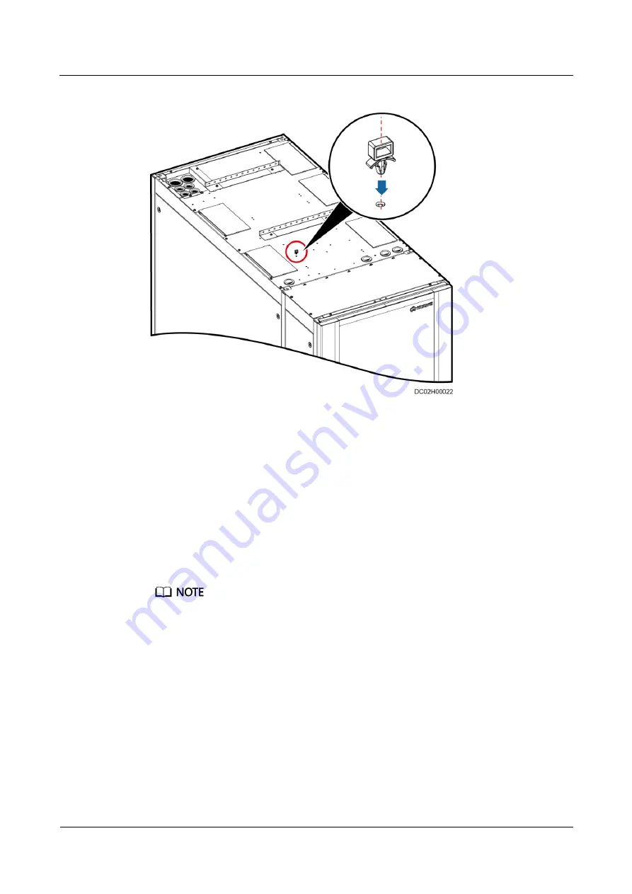
Figure 4-10
Installing a plastic cable tie
Emergency Fan Cable Route
The emergency fan components are installed at the top of the aisle containment by default.
The emergency fan power cable needs to be connected onsite, as shown in
1.
Remove the cover from the XT7 terminal block at the rear door of the Converged
Cabinet, as shown in
2.
Connect the fan components in series using the delivered cables.
3.
Connect the cables delivered with fan components from the power ports on the two
outermost fan components of the Smart Module to the XT7 terminal block at the rear
door of the Converged Cabinet.
Connect cables based on the cable labels and silk screens on the XT7 terminal block.
The XT7–5 and XT7–7 terminals on the XT7 terminal block are 48 V (+) ports, and the XT7–6 and
XT7–8 terminals are 48 V (–) ports.


