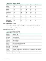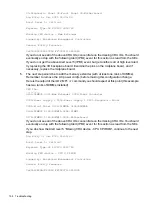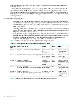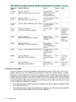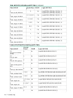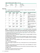
Table 53 Processor Events That May Light Diagnostic Panel LEDs (continued)
Notes
Source
Cause
Sample IPMI Events
Diagnostic
LED(s)
with
processor
SFW
A processor
failed
Type E0h, 34d:26d BOOT_CPU_FAILED
Processors
SFW
A logical
CPU (thread)
Type E0h, 33d:26d BOOT_CPU_EARLY_TEST_FAIL
Processors
failed early
self test
Possible
seating or failed
processor
BMC
No physical
CPU cores
present
Type 02h, 25h:71h:80h MISSING_FRU_DEVICE
Processors
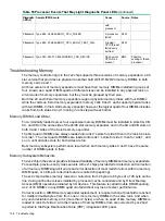
Troubleshooting Memory
The memory controller logic in the zx2 chip supports three versions of memory expanders: a 48
slot version that provides six physical ranks that hold 4/8/12/16/20/24 memory DIMMs in both
memory cells 0 and 1.
All three versions of memory expanders must have their memory DIMMs installed in groups of
four, known as a quad. DIMM quads of different sizes can be installed in any physical rank on
all versions of memory expanders, but they must be grouped by their size.
Both the 24 and 48 slot memory expanders support physical memory ranks with four DIMMs
while the common 8 slot memory expander’s memory cells 0 and 1 each support physical ranks
with two DIMMs. In the 8 slot memory expander, however, the logical quad of four DIMMs includes
ranks from both sides 0 and 1 running in lock step with each other.
Memory DIMM Load Order
For a minimally loaded server, four equal-size memory DIMMs must be installed in slots 0A, 0B,
0C, and 0D on the same side of the 24/48 slot memory expander; and in the 0A and 0B slots on
both 0 and 1 sides of the 8 slot memory expander.
The first quad of DIMMs are always loaded into rank 0’s slots for side 0 then in the rank 0’s slots
for side 1. The next quad of DIMMs are loaded into rank 1’s slots for side 0, then for side 1, and
so on, until all ranks slots for both sides are full.
Best memory subsystem performance result when both memory sides 0 and 1 have the same
number of DIMM quads in them.
Memory Subsystem Behaviors
The zx2 chip in the server provides increased reliability of memory DIMMs and memory expanders.
For example, previous entry class servers with zx1 chips provided error detection and correction
of all memory DIMM single-bit errors and error detection of most multi-bit errors within a memory
DIMM quad, or 4 bits per rank (this feature is called chip sparing).
The zx2 chip doubles memory rank error correction from 4 bytes to 8 bytes of a 128 byte cache
line, during cache line misses initiated by processor cache controllers and by Direct Memory
Access (DMA) operations initiated by I/O devices. This feature is called double DRAM sparing,
as 2 of 72 DRAMs in any DIMM quad can fail without any loss of server performance.
Corrective action, DIMM/memory expander replacement, is required when a threshold is reached
for multiple double-byte errors from one or more memory DIMMs in the same rank. And when
any uncorrectable memory error (more than 2 bytes) or when no quad of like memory DIMMs is
loaded in rank 0 of side 0. All other causes of memory DIMM errors are corrected by zx2 and
reported to the Page Deallocation Table (PDT) / diagnostic LED panel.
158
Troubleshooting

