background image

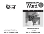
3.2.1 Console switch and control lamps

1  -  Travel system enable switch 

2  -  Parking brake enable switch

3  -  General engine fault

4  -  Charge control lamp 150A

5  -  Charge control lamp II 65A

6   -  General release for rear axle steering

7  -  Steering type: All-wheel drive

8  -  Steering type: Crab walk

Operation of enabling switch

The enabling switches are locked to pre

-

vent accidental actuation.

To operate the enable switch (1) push the locking (2) 

forward and press the release switch.

1

2

2

1

3

4

5

8 7 6

3.2.1.1 Enable switch: Travel drive

Actuation releases the travel drive (position I).

With the travel drive enabled (posi

-

tion I), the engine cannot be started.

There should not be any persons in 

the immediate danger zone around 

the machine when actuating the travel 

drive switch!

on

off

46

Содержание 80910205

Страница 1: ...READ CAREFULLY PRIOR TO STARTING UP KEEP OPERATING INSTRUCTIONS IN A SAFE PLACE ART ISSUE OPERATING INSTRUCTIONS LEEB PT 280 80910205 04 2015...

Страница 2: ......

Страница 3: ...hould return the acknowledge ment of receipt to HORSCH LEEB AS This confirms your formal acceptance of the machine The warranty period for the machine starts with the date of delivery You should only...

Страница 4: ...all relevant fundamental health and safety requirements of the EC directive 2006 42 EC For proper implementation of the heath and safety requirements mentioned in the EC directive the following stand...

Страница 5: ...tems GmbH Phone 49 0 99 37 95 96 30 Plattlinger Str 21 Fax 49 0 99 37 95 96 366 D 94562 Oberp ring Germany E Mail info leeb horsch com Type plate and CE identification Arrangement of type plate and CE...

Страница 6: ...em Check the error log Fill up fuel AdBlue Brake test Explanations during vehicle handover Raise the attention for safety regulations in operating instructions and on vehicle Inform about the necessit...

Страница 7: ...nstructions for the machine specified above I have been instructed by a Service Engineer of HORSCH LEEB AS HORSCH or an authorized dealer in the operation and functions as well as the safety related r...

Страница 8: ...8...

Страница 9: ...Hitching and unhitching a trailer 29 2 7 3 Using the machine 29 2 7 4 Changing equipment 30 2 7 5 Transporting the machine 30 2 7 6 Hydraulic system 30 31 2 7 7 Electric system 31 2 7 8 Battery 31 2...

Страница 10: ...s and display elements 55 3 7 2 Operation 56 3 7 2 1 Switching the system on 56 3 7 2 2 Adjusting the desired cabin temperature 56 3 7 2 3 Switching air conditioning operation on off 57 3 7 2 4 Switch...

Страница 11: ...ment 78 6 3 Engine oil level 78 6 4 Fuel and AdBlue level 78 6 5 Hydraulic oil level 79 6 6 Engine coolant control 79 6 7 After longer periods of rest 79 6 8 Tyres 79 6 9 Inspections inside the cabin...

Страница 12: ...101 10 2 Commander Box control unit 102 10 2 1 Suction side 102 10 2 2 Pressure side 102 10 2 3 Filling 102 10 2 4 Outside cleaning 102 10 3 Illuviation valve 103 10 4 Hand wash fresh water tank 104 1...

Страница 13: ...preparations and carbamide 131 12 5 3 Flushing in with ECOFILL optional 131 12 5 4 Pre cleaning the canister with wash 132 12 5 5 Pre cleaning the canister with rinsing water 132 12 6 Spraying 133 12...

Страница 14: ...r 164 14 12 Notes on maintenance work on axle and brakes 165 166 14 13 Axles 166 14 13 1 Maintenance of planetary gear unit 167 14 13 2 Maintenance of differential gear 167 14 14 Parking brake adjustm...

Страница 15: ...100 operating hours 189 19 1 5 Every 500 operating hours 190 19 1 6 Every 1000 operating hours or 1x per year 190 19 1 7 As required 190 19 1 8 Annually 190 19 2 Electric lighting system replacement...

Страница 16: ...timally familiar with the machine A Terminal box B Pendulum suspension C Wash container D Filling dome E Working platform F Railing access ladder left hand side G Spraying boom H Rape blossom protecti...

Страница 17: ...re filter Centrifugal pump Filling valve Flow meter Internal cleaning Wash container Piston diaphragm pump Suction filter Suction filter Air 1bar 10 bar Electric control valves Pressure sensor 1 2 Flu...

Страница 18: ...ection indicators right and left B 2 warning boards rectangular mud guards right and left rear F 2 direction indicators G 2 reversing headlights H 2 brake lights I 1 number plate holder with lighting...

Страница 19: ...boom 7 pieces 6 Railing on working platform Railing and access ladder to working platform and to reach the filler dome Strictly make sure that the access lad der is locked in transport position DANGER...

Страница 20: ...rsely affect occupational safety must be eliminated immediately Defective or excessively strained parts must be replaced immediately The machine must otherwise not be operated Use only genuine HORSCH...

Страница 21: ...e different crop protection products Substances with a tendency to agglutination or solidification must not be applied When using such aggressive crop protection products it is highly recommended to s...

Страница 22: ...ion max total weight in field kg 21 000 depending on tyres max perm axle load on road kg front rear 10 000 11 000 max perm axle load in field kg 18 000 theoretical Ground clearance mm 850 under axle w...

Страница 23: ...Outer planetary axle rigid or steerable Suspension FA and RA pneumatic with level control and active side stabilization Steering Front axle hydraulic Rear axle hydraulic electric steering with steerab...

Страница 24: ...t from floor mm 3 500 Volume of hand wash container l 15 Permissible system pressure bar 10 Technical residual quantity incl pump on level ground l 40 contour line 8 5 travel direction to the left l 4...

Страница 25: ...6240 4780 4560 4560 Standard tyres front rear 2 4 6560 5030 4750 4750 Alliance 50 480 80 R 50 2 8 7140 5470 5210 5210 3 2 7730 5920 5600 5600 Tyre type perm V max Tyre pressure Max perm tyre load in k...

Страница 26: ...ath or severe physical injuries loss of limbs or long term damage if not avoided Failure to comply with these notices can lead to fatal or most severe physical injuries WARNING identifies a possible m...

Страница 27: ...kplace The machine must solely be operated by one person sitting on the seat of the Trac 2 5 Danger caused by failing to comply with the safety regulations Failing to comply with the safety notes can...

Страница 28: ...ht and transport dimensions Check and install transport equipment such as e g lighting warning facilities and possible protec tive features Operating elements ropes chains linkages etc which are far a...

Страница 29: ...ther parts Triggering ropes for quick release couplings must hang down loosely and should not trigger any ac tion whne in lowest position Always ensure stability when parking unhitched trailers 2 7 3...

Страница 30: ...required transport equipment like e g lighting warning facilities and protective features has been correctly mounted to the machine Match your travel speed to the prevailing conditions 2 7 6 Hydraulic...

Страница 31: ...rst and the negative pole after When disconnecting disconnect the negative pole first and the positive pole after Always cover the positive pole of the battery with the cover intended for this purpose...

Страница 32: ...rac shows 0 5 bar Before hitching up the trailer you must clean the seal rings on the coupling heads of the supply and brake lines from any possible dirt Before driving without a machine hitched up cl...

Страница 33: ...not step close to the machine during this phase Work on the machine may only be started once the machine is fully at standstill Cleaning lubrication and adjustment work must only be carried out with...

Страница 34: ...protection products you may need to consult a physician Only fill the crop protection sprayer by using the original HORSCH LEEB AS filling equipment and only by gravity feed via the water supply 2 7...

Страница 35: ...ission WARNING Danger of crushing cutting being caught being pulled in and impact caused by the breakage of load bearing components The following is generally prohibited drilling in frame or undercarr...

Страница 36: ...tional safety of the vehicle 2 15 Dangers caused by residual energy Pay attention to the occurrence of mechanical hydrau lic pneumatic and electric electronic residual energies on the machine Apply ap...

Страница 37: ...the attachment location on the machine provide information about the special danger spots on the machine Keep all warning signs on the machine in clean and legible condition Replace illegible warning...

Страница 38: ...ers on the machine 04001457 04001454 Right side of machine Left side of machine under cover on and under engine cover 04002983 04001455 04001456 04001455 04001453 04001679 04001682 04001683 04002628 0...

Страница 39: ...04002623 04003745 04003747 04002625 04002626 39...

Страница 40: ...nd enters into the body Never try to seal off leaking hydraulic hoses with your hands or fingers Before starting maintenance and repair work on hydraulic hoses you should read and fol low the notes in...

Страница 41: ...because the machine might immediately start to move Order No Collective sticker 04002983 1x Order No Individual sticker 04001457 1x Danger of hand or arm being pulled in or caught by driv en unprotec...

Страница 42: ...These endangerments can cause severe and pos sibly also fatal injuries Persons are not permitted to remain under sus pended loads or raised parts of the machine Keep a sufficient safety distance from...

Страница 43: ...r use the clear water from the hand wash con tainer as drinking water Order No 04002628 1x Fill the hand wash container only with clear water never with crop protection products Order No 04001456 1x D...

Страница 44: ...44...

Страница 45: ...p for roof console 3 Device for camera monitoring optional 4 Info terminal 5 Multi function lever 6 Switch console 7 Steering column 8 Service brake 3 2 Switch console 1 Console switch 2 Control lamps...

Страница 46: ...ration of enabling switch The enabling switches are locked to pre vent accidental actuation To operate the enable switch 1 push the locking 2 forward and press the release switch 1 2 2 1 3 4 5 8 7 6 3...

Страница 47: ...the actuation lock A up and switch the switch to position 2 Driving on public roads using any of the possible rear axle steering modes of the self propelled machine is gen erally prohibited 3 2 1 3 E...

Страница 48: ...up complet ely and held during travel 3 2 3 Control lamps Differential lock When actuating the differential lock the control lamp 1 will light up Spaying BoomControl active optional When the BoomCont...

Страница 49: ...lighter 1 in depressed position to avoid damage Press the cigarette lighter 1 down once the required temperature is reached it will automatically pop out again The socket of the cigarette lighter can...

Страница 50: ...ght up D Half widths from left off E Half widths from left on F Half widths from right off G Half widths from right on H Slope compensation left or angular lift left down J Folding boom down or angula...

Страница 51: ...deceleration in forward start of travel drive with activation button R depressed D Changeover for angular lift functions E Travel joystick in middle position F Distance control Automatic on off G No a...

Страница 52: ...only 5 Working headlights rear end fender bottom 6 Parking light dipped headlight 7 Flashing beacons 8 Hazard light system 9 Front windscreen wipers 10 Front windscreen washer system 11 Working headl...

Страница 53: ...flasher 6 Travel light control lamp 7 Trailer function control lamp 8 Unlocking lever for horizontal steering column adjustment 9 Unlocking lever for horizontal and vertical steering column adjustmen...

Страница 54: ...backward left hand indicator Move switch manually to neutral position The indicator control lamp 3 lights when the indicator is switched on 3 6 4 Travel light Travel light only with dipped headlight s...

Страница 55: ...sired cabin temperature Alternatively Manual settings up 3 Button to lower the desired cabin temperature Alternatively Manual settings down 4 Button to switch the control on and off 5 Toggle button ev...

Страница 56: ...itioning system then appear for another 5 seconds e g 6 operating hours The setting saved last subsequently appears in the display 3 7 2 2 Adjusting the desired cabin tem perature The set cabin temper...

Страница 57: ...4 Switching REHEAT operation on off REHEAT operation demoisturizing of cabin air Press button to switch on REHEAT operation The display shows the following REHEAT operation has been switched on the sy...

Страница 58: ...ton or re duced with button in 10 steps The lowest adjustable fan speed is 30 the display shows 3 bars Pressing the button two times AUTO mode is reactivated the symbol AUTO is displayed again the sym...

Страница 59: ...e of a sensor fault the control will continue work with the setting that was valid before the fault was detected Error code FI A fault of the blow out temperature sensor is indicated by a flashing dis...

Страница 60: ...he engine down immediately Check the oil level if necessary consult the Cus tomer Service 3 8 2 Charge control lamps The charge control lamps 2 and 3 light up if the out put voltage from the three pha...

Страница 61: ...nal 1 Terminal on off terminal starts automatically through the ignition 2 Acknowledgement key menu key 3 Display 4 Selection button 5 Function keys 6 no function 7 no function 8 Change header 9 Chang...

Страница 62: ...ifferential lock Oil temperature in hydraulic oil tank System pressure compressed air System pressure hydrostatic drive 1st gear field operation gear change only possible with the machine stopped 2nd...

Страница 63: ...ask manufacturer for code 3 10 1 1 Settings auto turn Engine speed activate deactivate only in travel mode I Tempomat activate deactivate only in travel mode I III Rear axle steering activate deactiva...

Страница 64: ...ses for 100 m Use arrow key to leave to DIN 2 The counter is now set to 0 Drive a distance of 100 m and read the value You can now enter the value in the parameter page see under 4 5 1 When re opening...

Страница 65: ...t in exhaust gas after treatment The warnings can appear in various combinations flash ing or permanently lighting Depending on the nature of a fault the engine power can be reduced down to 20 in conn...

Страница 66: ...ight glass Hydraulic oil level 13 Hydraulic oil level too low Remedy Fill up hydraulic oil and seal possible leaks immediately Hydraulic oil temperature 14 Temperature of hydraulic oil too high Remedy...

Страница 67: ...tors 1 3 will flash together Brake light The brake lights 4 light up if the service brake is operated with the ignition switched on when using the travel lever for braking Side lights The front side l...

Страница 68: ...e light 4 3 Dipped headlight Switching on the dipped headlight The toggle switch 6 for the parking light and dipped headlight is located in the group of switches in the roof console It has three posit...

Страница 69: ...ole 1 Working headlights on roll over protection structure behind cabin left and right top 2 Working headlights cabin roof front top 3 Working headlights front apron 5 Rear working headlights fender b...

Страница 70: ...con 1 Rotating beacon 7 7 4 6 NightLight optional Extremely bundled light LED spotlight to illuminate the spraying cones The lights are automatically cleaned by a washing system 2 after operating the...

Страница 71: ...dstill When operating make sure that there are no persons in the danger zone Button must be pressed for fol ding the access ladder The but ton must be pressed for at least 5 seconds for the access lad...

Страница 72: ...iver s seat 1 moves up Push the lever 6 carefully completely down po sition II the driver s seat 1 moves down If the top or bottom end stop of the height adjustment is thereby reached the height will...

Страница 73: ...e hexagon nut move the armrest to the desired position and retighten the hexagon nut Press the covering cap 12 back on to the hexagon nut Adjustable vibration damper With the vibration damper which ca...

Страница 74: ...sition When releasing the pedal 2 the steering column is locked 1 Horizontal steering column adjustment Loosen the unlocking lever 3 Move the steering column 1 to the desired position Retighten the un...

Страница 75: ...ooling box the cooling box can be connected to the 12 V socket outlet 3 to the right of the passenger seat 5 9 Sun visor Adjust the position of the sun visor 1 as required 2 1 1 1 3 5 6 Instructor s s...

Страница 76: ...ar view mirror is electrically adjustable The switch 4 is located in the roof console Adjusting the left hand outside rear view mirror and the travel start mirror Adjust the travel start mirror so tha...

Страница 77: ...14 Adjustable air nozzles The front roof section of the cabin is equipped with six manually adjustable air nozzles 1 Two more manually adjustable air nozzles 2 are located in the rear roof section of...

Страница 78: ...rk The oil level should always be between the bottom and top marks The machine must be parked on level ground to check the oil level The oil level can be checked by the dipstick 1 left side of engine...

Страница 79: ...ide 6 6 Engine coolant control Remove the cap 2 to check the engine coolant The coolant must reach the upper edge More detailed information can be found in the chapter Service and Maintenance 6 7 Tyre...

Страница 80: ...u release the corresponding actuator This does not apply for equipment which are continuous or automatically controlled or require a floating or pressure position because of their function 7 1 Check s...

Страница 81: ...d rolling of the machine Secure Trac and machine against accidental starting and unintended rolling before starting work on the machine All interventions on the machine such as e g assembly work adjus...

Страница 82: ...82...

Страница 83: ...e of overheating Do not open the cap 1 while the engine is hot Shut down the engine and wait until the engine has cooled down Completely remove the cap see chapter Engine coolant inspection Check the...

Страница 84: ...pre vent accidental actuation To operate the enable switch 1 push the locking 2 forward and press the release switch Enabling switches Travel drive Actuation releases the travel drive position I With...

Страница 85: ...ws the basic screen 8 5 Starting the engine Only start the engine from the driver s seat Turn the ignition key 1 to position III Once the engine starts release the key immediately Never keep the key i...

Страница 86: ...system Always connect the plus pole first and the minus pole after 8 6 Engine fault control lamp The engine fault control lamp 1 light up if the engine oil pressure is too low or in case of a fault S...

Страница 87: ...g temperature restart it immediately to avoid an unnecessary accumulation of heat on important function parts Allow the engine to run for another 1 to 2 minutes before shutting it down 8 11 In case of...

Страница 88: ...ealer With an actuated quick stop button driving is no longer possible Unlock the quick stop button by turning it anti clockwise 9 2 Starting the engine Details see chapter 8 Engine operation 9 3 Brak...

Страница 89: ...tion Make yourself familiar with the changed steering conditions Operating controls steering switch console A General release for rear axle steering B Steering type Crab walk C Steering type All wheel...

Страница 90: ...l steering via foot switch jog mode for headland Activate the switch A General release of rear axle steering Rear axle steering is unlocked and electro hydraulically held in centred position Actuate t...

Страница 91: ...lever backward the machine will decelerate until it is positively stopped Starting to drive backward from standstill After starting the engine the gearbox is in 1st gear Enabling travel operation must...

Страница 92: ...e I or II to travel mode III 9 6 1 Setting function Travel mode I Travel lever pedal 1 Speed control via travel lever Retrieve engine speed control via keypad A B on console or foot pedal see also cha...

Страница 93: ...is au tomatically regulated In this mode you have a Tempo mat function available The saved Tempomat speed is displayed next to the travel mode symbol and approach es with an as low as possible engine...

Страница 94: ...age I or the fastest in acceleration stage IV Switch position I slow acceleration Switch position IV fast acceleration 9 8 Tempomat With the Tempomat the saved speed is automatically approached Saving...

Страница 95: ...power of the oil cooler This reduces the oil temperature The drive torque working on the drive wheels depends on the oil pressure in the hydrostatic drive If the required pressure exceeds the pressur...

Страница 96: ...teristics of the Trac and the influences of a trailer WARNING Danger of breakage during operation insufficient stability and inadequate steering and brak ing ability of the Trac if used for purposes o...

Страница 97: ...public roads is only permit ted with the boom folded in and placed in its receptacle Transport lock on boom receptacle Before starting road transport make sure that the boom rests securely in the fron...

Страница 98: ...ng brake when released oil pressure available Turn in the setscrew until higher resistance can be felt The brake linings now touch the brake disc Now back out the set screw for half a turn This will l...

Страница 99: ...e system must be used When pulling a loaded trailer to not use the travel lever for excessive brak ing If high deceleration is required use the service brake because in this case the trailer will brak...

Страница 100: ...of crushing between Trac and trailer when coupling the machine Expel persons from the danger zone between Trac and trailer before you move the tractor towards the trailer With the automatically workin...

Страница 101: ...praying operation or out of the fresh water tank to clean the spraying system In spraying operation the sucked in fluid is directed to the pressure filter 2 and flows then through the flow meter into...

Страница 102: ...ector illuviation valve OFF ON Pressure agitator Inside cleaning OFF ON 10 2 3 Filling 3 Quit filling process OFF Start filling process ON Hold switch in position ON Feeding function More detailed inf...

Страница 103: ...lling connection ECOFILL 9 Separating web in extraction area 10 Pressure plate 11 Rotating canister flushing nozzle to flush out canis ters or other containers 12 Closed loop line to dilute and illuvi...

Страница 104: ...ll clear water into the hand wash tank 1 WARNING Danger of poisoning by contaminated water in the fresh water tank Never use the water from the fresh water tank as drinking water The materials of the...

Страница 105: ...ation valve The pump must never be operated without fluid since this would damage the seals Technical data pump equipment Type l min l min Maximum at 0 bar at 8 bar pressure design dependent bar _____...

Страница 106: ...very and clean the filter element reinsert the element and screw the filter cap back on 3 Pressure filter cleaning connection 10 9 Agitator The wash container is equipped with an agitator This agitato...

Страница 107: ...to use a more coarse element in order keep the pressure drop inside the filter as low as possible The self cleaning pressure filter prevents clogging of the nozzle filters in front of the spraying no...

Страница 108: ...m 10 12 Outside washing facility optional High pressure cleaner to clean the crop protection sprayer including 1 hose reel 2 20 m pressure hose 3 spray gun Operating pressure 150 bar Water output 15 l...

Страница 109: ...Both tanks are made of stainless steel The wash container is equipped with the pressure agitator 10 15 Fresh water tank a Fresh water tank total contents 450 litres b Filling connection c Ventilation...

Страница 110: ...filling the wash container through the suction hose from open water tapping points The suction hose 3 with quick release coupling and check valve prevents the drainage of the fluid quantity that is a...

Страница 111: ...ed in being caught or impact for third parties may arise if third parties remain in the operating range of the boom when unfolding or folding the boom and are caught by the moving parts of the boom Ex...

Страница 112: ...eight Folding the spray boom e Lift the boom against the end stop f Fold the outside wings g Fold the inside wings h Place the boom into the transport lock More detailed information about the operatio...

Страница 113: ...e caught by the boom when lifting or lowering for height adjustment Expel persons from the danger zone of the machine before lift or lower the spray boom with the height adjustment Adjust the spraying...

Страница 114: ...ce to maintain the exact lowest possible working height even when driving with high speed and in highly cropped terrain This creates the prerequisite for mini mum drifting Active adaptation of the boo...

Страница 115: ...n with the transport lock before start ing transport travels Use the transport safety straps serve the purpose of locking the folded up spray boom in transport position to prevent accidental unfolding...

Страница 116: ...om sections the pipe is continuous The sections are coupled by hoses resulting in continuous lines over the entire width of the boom The nozzle con trol has been designed as pneumatic single nozzle co...

Страница 117: ...idths 100 l ha 83 m 250 l ha 33 m _______________________________________________________ 150 l ha 55 m 300 l ha 28 m _______________________________________________________ 200 l ha 41 m 400 l ha 20...

Страница 118: ...is recommended if more than only one nozzle type is to be used Only the vertically arranged nozzle will be supplied By turning the nozzle body another nozzle is brought into use In intermediate posit...

Страница 119: ...connection 9 Bayonet cap 10 Nozzle body 11 11 4 Edge nozzles electric optional With the edge nozzle control the last nozzle is switched off and an edge nozzle 25 cm further to the outside exactly mat...

Страница 120: ...and small drops enhance the magnifying glass effect Due to the salt concentration of the fertiliser excessive application of fertilizer can cause cauterisation on the leaves 3 yet nozzles optional The...

Страница 121: ...mple ment and possibly also trailer Be aware of your own abilities account for the road traffic sight and weather conditions the driving characteristics of the Trac and the influences of the sprayer i...

Страница 122: ...prescribed filters Clean the filters at regular intervals Trouble free operation of the crop pro tection sprayer is only ensured with optimal filtration of the wash Appropriate filtering considerably...

Страница 123: ...otection product canisters and contaminated crop protection spray er against precipitation Ensure sufficient cleanliness during and after work for preparing wash to keep any risks as low as possible e...

Страница 124: ...B 1 0 l Question How many l of water how many kg or product A and how many l of product B do you have to fill in if the area to be treated is 2 5 ha Answer Water 400 l ha x 2 5 ha 1000 l Product A 1 5...

Страница 125: ...7 8 8 10 11 11 12 13 13 14 50 9 10 11 12 14 14 15 16 17 18 60 11 12 13 14 16 17 18 19 20 22 70 13 14 15 17 19 20 21 22 23 25 80 14 16 17 19 22 22 24 26 26 29 90 16 18 19 22 24 25 27 29 30 32 100 18 20...

Страница 126: ...urfaces so that no wash runs into the sewer system No foam should escape from the wash container during filling A large cross section funnel that reaches down to the bottom of the wash container most...

Страница 127: ...y of filling is at the edge of the field from the water tanker if possible make use of a natural inclination Depending on the crop protection product used this filling method is not allowed in water p...

Страница 128: ...all valve 1 4 Start the filling process set the switch 2 on the C Box to ON 5 The pump switches off automatically when the desired filling level is reached You can interrupt the filling process at any...

Страница 129: ...spraying The information provided by the preparation manufacturer are decisive in this respect Insert water soluble foil bags directly into the wash container while the agitator is running Flush the...

Страница 130: ...ear water is applied to the illuviation valve Should the desired container contents be reached during the illuviation the suction valve will automatically switch over to the wash container In this cas...

Страница 131: ...ball valve again 10 Switch off the injector 11 Adjust the desired agitator power 12 Fill in the missing amount of water 12 5 3 Flushing in with ECOFILL optional 1 Fill the wash container half with wa...

Страница 132: ...econds 7 Close the ball valve again 8 Switch off the injector 12 5 5 Pre cleaning the canister with rins ing water Cleaning the canister with rinsing water dilutes the con centration of the wash 1 Set...

Страница 133: ...fine medium or coarse drops of the crop protection product used for the crop protection measure to be carried out See also chapter 21 Spraying tables for flat jet anti drift injector and airmix nozzl...

Страница 134: ...on the automatic area related application quantity control The agitator normally remains switched on from filling to the end of spraying The information provided by the preparation manufacturer are d...

Страница 135: ...al check the value Pulses per 100 m 8 In the terminal check the values max pressure and min pressure for the permissible spraying pressure range with the spraying nozzles installed in the spraying boo...

Страница 136: ...ns for the corresponding crop protection product 12 6 5 Spraying with 25cm nozzle spacing and reduced distance to the target area The risk of windward drifting can be considerably reduced by reducing...

Страница 137: ...y 100 litres With the agitator switched on the technical residual quantity increases in contrast to the specified values Measures to protect the user must be applied when emptying residual quantities...

Страница 138: ...echnical residual quantities 1 Place a suitable collecting vessel under the cap of the suction filter 1 2 Open the cap and drain the technical residual quantity into a suitable collecting vessel 3 Clo...

Страница 139: ...tank contents 15 l 2 Drain tap for clear water to clean the hands or to clean the spraying nozzles WARNING Danger of poisoning by contaminated water in the fresh water tank Never use the water from t...

Страница 140: ...he suction port for leakage Pump does not generate any power Jammed or damaged ball valves Replace the ball valves Pump draws in air noticeable air bubbles in the wash container Check the hose connect...

Страница 141: ...ce of maintenance and repair work under moveable parts of the ma chine which are in raised position is only permitted if these machine parts have been positively secured against accidental lowering Be...

Страница 142: ...ing repair work Generally perform repair work on the crop protection sprayer with non driven pump Repair work inside he wash container must only be carried out after thorough cleaning Do not climb int...

Страница 143: ...r Regular cleaning of the crop protection sprayer is a prerequisite for proper maintenance and eases operation of the crop protection sprayer Keep the exposure time as short as possible e g by daily c...

Страница 144: ...ister flusher using a suitable container until only clear water runs out 8 Switch on the closed circuit line until only clear water runs out 9 Switch on the shock nozzle for approx 10 seconds 10 Switc...

Страница 145: ...is not followed 13 5 Cleaning tank and outside of sprayer Inside tank cleaning 1 Set the suction side to fresh water 1 2 Switch of boom circulation injector and agitator 2 3 Switch on the pump on the...

Страница 146: ...oosen the spigot nut 5 Take off the filter bowl and pull out the filter element 6 Clean the filter element with water 7 Check the O rings for damage 8 Reassemble the suction filter in reverse order 13...

Страница 147: ...intaining this oil level is vital for the engine Check the oil level only with the machine parked horizontally Do not start the engine if the oil level is below the bottom dipstick mark Fill in oil up...

Страница 148: ...6 Fuel AdBlue Do not refuel or fill up AdBlue while the engine is running Smoking prohibited Quality and cleanliness of fuel are of fundamental impor tance for a uniform excellent power and a long lif...

Страница 149: ...llergic reactions you should immediately consult a physician Keep AdBlue out of the reach of children More detailed information can be found in the operating instructions for MTU diesel engines Fuels...

Страница 150: ...otection and anti freeze concentration in the coolant every half year Use only approved corrosion protection and antifreeze agents see chapter 19 5 table Fuels and lubricants of carrier vehicle Engine...

Страница 151: ...adiator cap 1 Fill in coolant to the upper edge of the filler neck Tighten the radiator cap 1 Check in the filler neck 1 If no fluid is visible Refilling required 14 1 11 Cleaning the cooling system A...

Страница 152: ...le in the display the main filter element needs to be replaced The warning symbol 2 in the display of the terminal signalises the degree of contamination of the filter cartridge see also operating ins...

Страница 153: ...ut no dust should enter the inside of the main element Do not use a damaged main element If in doubt use a new main element If the contamination indicator is still visible in the display after cleanin...

Страница 154: ...ources for the required information Check hydraulic hoses at regular intervals and replace these if damaged or aged The replace ment lines must comply with the technical requirements specified by the...

Страница 155: ...m the following list Damage to the outer layer to to the ply e g chafing cuts cracks Embrittlement of the outer layer formation of cracks in the hose material Deformations which do not correspond with...

Страница 156: ...ment and fastening If necessary protect hydraulic hoses with protective coverings Cover sharp edged com ponents the permissible bending radii are not exceeded When connecting a hydraulic hose to movin...

Страница 157: ...ps 1 Auxiliary steering pump Position above the front axle motion link 2 Travel pump Position behind diesel engine 3 LS pump for working hydraulics 4 Fan drive pump 5 Travel motor Position in front of...

Страница 158: ...ck is located on the upper side of the solution tank Vehicle hydraulics No Designation 10 LS line 11 Tank return flow 12 Parking brake operation 13 Pressure accumulator parking brake 14 Pressure switc...

Страница 159: ...ve 4 Pressure accumulator for service brake 5 Accumulator charge valve The valves are located on the underside of the cabin Steering hydraulics No Designation 1 High pressure filter 2 Priority valve 3...

Страница 160: ...e valves are located on the rear axle The valve is located on the underside of the cabin 2 Steering valve 14 5 LS shut off valve Have work on the LS shut off valve only performed by the Customer Servi...

Страница 161: ...stomer Service 14 6 1 Specification of mineral oils for the hydraulic system The following hydraulic oils have been approved for used HLP acc to DIN 51524 2 viscosity class ISO VG 46 HLP D acc to DIN...

Страница 162: ...vel must be between the level marks 14 8 Replacing the hydraulic oil filter Ensure strict cleanliness when changing the filter Replace the high pressure filteras follows Replace the high pressure filt...

Страница 163: ...st 100 operating hours Then every 1000 hours but at least 1x per year Oil change in manual transmission Unscrew the drain plug 1 Drain off all oil Catch the oil in a suitable vessel Retighten the oil...

Страница 164: ...14 11 Manual transmission coolant circuit 1 Transmission lubrication pump 2 Filter 3 Transmission oil cooler 1 3 2 164...

Страница 165: ...following criteria Pipe hose lines and coupling heads must not show any external damage or corrosion Joints e g on fork heads must be properly secured light moving and should not be worn Ropes and ac...

Страница 166: ...and check the clearance In case of noticeable bearing clearance Adjust the bearing clearance Remove the dust cap or the hub cap Remove the cotter pin from the axle nut Tighten the wheel nut while tur...

Страница 167: ...top up if necessary Screw the plugs 1 and 2 back in Tightening torque for the plugs 1 2 3 50 10 Nm You should only use LS gear oil API GL 5 MIL L 2105 B LS LS SAE90 Filling quantity per planetary gea...

Страница 168: ...ction see chapter 3 2 1 Position II Make sure that the vehicle will not acci dently start to drive Unscrew the covering cap 2 Loosen the counter nut 3 Turn the setscrew clockwise until the brake linin...

Страница 169: ...ar intervals on cold tyres i e before starting to drive chapter 1 8 The difference in tyre pressure between the tyres on one axle must not exceed 0 1 bar During fast travel or under warm weather condi...

Страница 170: ...new tubeless valves or tubes Always screw valve caps with integrated seal on the valves 510 Nm Never use the self propelled sprayer with the tyre pressure that is commonly used to ship the tyres Leav...

Страница 171: ...d V belt 1 14 18 Draining the compressed air system Drain the air vessel every day before starting work by pulling the drain valve 1 14 19 Windscreen washing system Open the cover 2 to fill the contai...

Страница 172: ...e front tank support Loosen the connecting hoses 3 and 4 to the illuviation valve Loosen the connecting hoses 5 and 6 Disconnect all electric plug connections 7 and 8 Loosen both hose clamps 9 on the...

Страница 173: ...11 7 8 9 10 173...

Страница 174: ...atteries before starting repair work welding work 16 3 Assisted starting See description in chapter 8 8 16 4 Battery danger in handling General Always keep batteries clean from dust and crop residues...

Страница 175: ...ttery and three phase alternator causes severe damage 16 7 Three phase alternators When working in the electric system disconnect the plus cable from the batteries to avoid damage Protect the cable co...

Страница 176: ...n the engine and tighten the connection to the engine Battery power too low Check for voltage drop on batteries if necessary re charge the battery Discharged battery Charge the battery Use of an incor...

Страница 177: ...ole Zentralstecker Fahrsteuerung Diverse Display R ckfahrkamera Feststellbremse Motorsteuerger t AdBlue Motorsteuerger t OBD Motorsteuerger t AdBlue STX2 Ladekontrolle K7 12V max 20A Kl 30 12V max 20A...

Страница 178: ...16 10 3 Cabin mounted PCB cabin roof The fuses are centrally located inside the cabin The relays are located in the junction box at the front right hand side under the console as well as on the fuse...

Страница 179: ...cabin roof middle Working headlights cabin roof left Working headlights cabin roof right Working head lights ejection arch rear end Working headlights platform Rear wheel illumination Working headligh...

Страница 180: ...rolling away Repair service maintenance and cleaning work must only be carried out by authorized experts When performing repair service maintenance and cleaning work on the refrigerant cir cuit refrig...

Страница 181: ...101 1 C Critical pressure 40 60 bar Density liquid at 25 C 1206 kg m3 Inflammability limits in air not inflammable Environmental data FKW 134a ODP Ozone Depletion Potential ODP 0 CLP Chlorine Loading...

Страница 182: ...Have maintenance and repair work on the air conditioning system solely carried out by your HORSCH sales partner using appropriate disposal and recycling facilities 17 6 Pressure switch With the highes...

Страница 183: ...should be visually examined for contamination be fore each travel operation In case of insufficient filter maintenance the filter may be excessively contaminat ed so that a sufficient fresh air supply...

Страница 184: ...ection with the inspections Special attention must thereby be paid to corrosion and mechanical damage Should the vessel not be in a fit state it must be replaced because of safety related reasons as a...

Страница 185: ...is possible Wet all lever joints and bearing points which are not subjected to lubrication slightly with oil Loosen the pressure gauges 1 on the coupling points Take off completely and store in a fros...

Страница 186: ...and pressure filter elements 5 Remove al nozzles and nozzle filters take out and clean the filter elements 6 Fill approx 30 litres of a permanent anti freeze water mix ratio 1 2 through the filler do...

Страница 187: ...eb PT 280 will rule out expensive malfunc tions during the season The self propelled sprayer must be thoroughly cleaned from inside and outside if this has not yet been done during the previous season...

Страница 188: ...188...

Страница 189: ...the first 100 operating hours Change engine oil and filter element Change hydraulic oil and filter elements Change oil in planetary and differential gears on front and rear axles Change the gear oil i...

Страница 190: ...ctions on the turbo charger for tight fit Clean the paper filter elements in the cabin Check PTO centralizer axle transfer boxes and axle for leak tightness 19 1 5 Every 500 operating hours Drain the...

Страница 191: ...____________________________________ M 14 22 135 190 230 M 14x1 5 150 210 250 __________________________________________________________________________________ M 16 24 210 300 355 M 16x1 5 225 315 38...

Страница 192: ...ponified multi purpose grease with EP additives Company Lubricant designation Standard application conditions Lubricant designation Extreme application conditions ARAL Aralub HL 2 Aralub HLP 2 FINA FI...

Страница 193: ...l Diesel fuel Replenishment after work Cooling system approx 16 l Mixture of 50 anticorrosive and antifreeze and 50 water mixing ratio and cooling fluid acc to table in MTU operating instructions pag...

Страница 194: ...ng nozzles Clean flush Weekly 50 operating hours Component Maintenance work Workshop work Hydraulic system Check for leaks X Folding boom Visual inspection of folding joints for zero clearance apparen...

Страница 195: ...flow meter Nozzles Perform volumetric measurement of the crop protection sprayer and check trans verse distribution replace worn nozzles if necessary As required Component Maintenance work Workshop w...

Страница 196: ...ly on the universal joints at both ends of the propshaft Total 4 piece Frequency every 30 operating hours Axle link bearing Grease nipple 2 Total 4 piece Frequency every 30 operating hours Axles steer...

Страница 197: ...Centre axle bolt Grease nipple 4 Total 1 piece Frequency every 100 operating hours Towing jaw Grease nipple 5 Total 1 piece Frequency every 100 operating hours 4 5 197...

Страница 198: ...regularly after approx 50 100 hours Folding boom middle section part B 11 lubrication points Lubricate regularly after approx 50 100 hours Tower rollers 1 lubrication point identical on either side 2...

Страница 199: ...ox 50 100 hours 19 8 2 Lubrication points folding boom 5 pieces Folding joint outer middle boom 7 lubrication points identical on either side 14 lubrication points in total lubricate regularly after a...

Страница 200: ...ly after approx 50 100 hours Folding joint middle section inner boom 7 lubrication points identical on either side 14 lubrication points in total lubricate regularly after approx 50 100 hours On 7 pie...

Страница 201: ...Control Plus 3 lubrication points identical on either side 6 lubrication points in total Lubricate regularly after approx 50 100 hours 19 8 5 Servicing the lifting ropes Grease or spray the lifting ro...

Страница 202: ...ased then every 4 half years Hose connection for pump test 1 available from the manufacturer Hose connection for flow meter test 2 available from the manufacturer Pump test pump capacity test 1 Plug t...

Страница 203: ...nk hoses and plastic fittings Metal parts can be scrapped Strictly follow the statutory regulations concerning the waste disposal of the individual materials Energetic utilization is the recovery of e...

Страница 204: ...haracteristic fine medium or coarse drops of the crop protection product used for the crop protection measure to be carried out The table on page 207 serves the purpose of determining the nozzle size...

Страница 205: ...km h Required atomizing characteristic for the crop protection measure to be carried out coarse drops no windward drift required nozzle type required nozzle size Required spraying pressure bar requir...

Страница 206: ...I or ID 4 Go to the spraying table on the following page 5 In the column with the intended travel speed 8 km h look for the required application quantity 200 l ha or an application quantity that comes...

Страница 207: ...lues apply for water of 20 C pressure measured directly at the nozzle Check the values with a measuring vessel before the start of application Example 200 l ha at 7 2 km h require 1 20 l min per nozzl...

Страница 208: ...raying table for 3 jet nozzles spraying height 120 cm permissible pressure range 1 3 bar Spraying table for 3 jet nozzles yellow Spraying table for 3 jet nozzles red Spraying table for 3 jet nozzles b...

Страница 209: ...table for 5 jet nozzles permissible pressure range 1 2 bar Spraying table for metering disc 4916 39 1 0 mm spraying height 100 cm for 5 hole nozzle black Spraying table for metering disc 4916 45 1 2 m...

Страница 210: ...able for metering disc 4916 63 1 6 mm spraying height 75 cm for 5 hole nozzle grey Spraying table for metering disc 4916 72 1 8 mm spraying height 75 cm for 5 hole nozzle grey 21 3 Spraying table for...

Страница 211: ...Spraying table for 7 hole nozzle SJ7 03VP blue Spraying table for 7 hole nozzle SJ7 04VP red Spraying table for 7 hole nozzle SJ7 05VP brown Spraying table for 7 hole nozzle SJ7 06VP grey 211...

Страница 212: ...able for 7 hole nozzle SJ7 08VP white 21 4 Spraying table for FD nozzles permissible pressure range 1 5 4 bar Spraying table for FD 06 nozzle Spraying table for FD 08 nozzle Spraying table for FD 10 n...

Страница 213: ...21 5 Spraying table for towed hose arrangement permissible pressure range 1 4 bar Spraying table for metering disc 4916 26 0 65 mm Spraying table with metering disc 4916 32 0 8 mm 213...

Страница 214: ...Spraying table for metering disc 4916 39 1 0 mm standard Spraying table for metering disc 4916 45 1 2 mm Spraying table for metering disc 4916 55 1 4 mm 214...

Страница 215: ...ersion table for spraying liquid fertiliser ammonium nitrate carbamide solution AHL Density 1 28 kg l i e approx 28 kg N for 100 kg liquid fertiliser or 36 kg N for 100 litres of liquid fertiliser at...

Страница 216: ...216...

Страница 217: ......

Страница 218: ...pplication Systems GmbH Plattlinger Stra e 21 D 94562 Oberp ring Tel 49 9937 95963 0 Fax 49 9937 95963 66 E Mail info leeb horsch com All details on technical specifications and pictograms are approxi...

Отзывы: