L200
2
Inverter
Conf
igur
ing
Dr
iv
e P
a
ra
m
e
ters
3–45
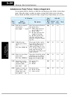
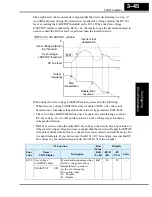
The graph below shows an inverter output profile that starts decelerating to a stop. At
two different points during the deceleration, regenerative voltage elevates the DC bus
level, exceeding the LADSTOP threshold set by B131. When the Over-voltage
LADSTOP feature is enabled by B130 = 01, the inverter stops the deceleration ramp in
each case until the DC bus level is again less than the threshold value.
When using the Over-voltage LADSTOP feature, please note the following:
• When the over-voltage LADSTOP feature is enabled (B130 = 01), the actual
deceleration is sometimes longer than the value set by parameters F003/F203.
• The over-voltage LADSTOP feature does not operate by maintaining a constant
DC bus voltage. So, it is still possible to have an over-voltage trip event during
extreme deceleration.
• If B131 is set
lower
than the normal DC bus voltage (when
not
in decel) by mistake, or
if the inverter’s input voltage increases enough, then the inverter will apply LADSTOP
(if enabled) all the time. In this case, the inverter can accelerate and run the motor, but
it cannot decelerate. If you are not sure that B131 > DC bus voltage, measure the DC
bus voltage in your installation and verify that the B131 value is higher.
OVLADSTOP = enable
B130 = 01
Output
frequency
t
t
Over-voltage protection
trip threshold
DC bus level
B131
Over-voltage
LADSTOP threshold
V
Inverter stops
deceleration
Deceleration
resumed
Start
deceleration
“B” Function
Run
Mode
Edit
Lo Hi
Defaults
Func.
Code
Name /
SRW Display
Description
–FE(F)
(EU)
–FU
(USA)
Units
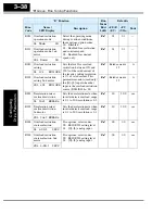
B130 Over-voltage
LADSTOP enable
Pauses deceleration ramp when
DC bus voltage rises above
threshold level, in order to
avoid over-voltage trip.
Two option codes:
00 .. Disable
01 .. Enable
✘ ✔
00
00
—
OVLADSTOP OFF
Содержание L200-002NFE2
Страница 2: ......
Страница 46: ......
Страница 80: ......
Страница 204: ......
Страница 205: ...Inverter System Accessories In This Chapter page Introduction 2 Component Descriptions 3 Dynamic Braking 5 5 ...
Страница 212: ......
Страница 229: ...Glossary and Bibliography In This Appendix page Glossary 2 Bibliography 8 A ...
Страница 280: ......
Страница 281: ...Drive Parameter Settings Tables In This Appendix page Introduction 2 Parameter Settings for Keypad Entry 2 C ...
Страница 293: ...CE EMC Installation Guidelines In This Appendix page CE EMC Installation Guidelines 2 Hitachi EMC Recommendations 6 D ...
Страница 297: ...L2002 Inverter Appendix D D 5 L1 L2 L3 PE L2002 inverter with book type filter M 3 ...

