Network Protocol Reference
Appendix B
B–8
Message Configuration: Response
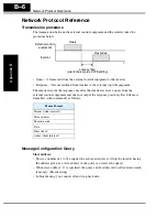
Transmission time required:
• A time period between reception of a query from the master and transmission of a
response from the inverter is the sum of the silent interval (3.5 characters long) + C078
(transmission latency time).
• The master must provide a time period of the silent interval (3.5 characters long or
longer) before sending another query to an inverter after receiving a response from the
inverter.
Normal response:
• When receiving a query that contains a function code of Loopback (08h), the inverter
returns a response of the same content of the query.
• When receiving a query that contains a function code of Write in Register or Coil
(05h, 06h, 0Fh, or 10h), the inverter directly returns the query as a response.
• When receiving a query that contains a function code of Read Register or Coil (01h or
03h), the inverter returns, as a response, the read data together with the same slave
address and function code as those of the query.
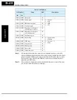
Response when an error occurs:
• When finding any error in a query (except for a transmission error), the inverter
returns an exception response without executing anything.
• You can check the error by the function code in the response. The function code of the
exception response is the sum of the function code of the query and 80h.
• The content of the error is known from the exception code.
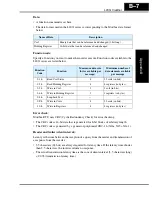
Field Configuration
Slave address
Function code
Exception code
CRC–16
Exception
Code
Description
0 1 h
The specified function is not supported
0 2 h
The specified address is not found.
0 3 h
The format of the specified data is not acceptable.
2 1 h
The data to be written in a holding register is outside the inverter.
2 2 h
The specified functions are not available to the inverter.
•
Function to change the content of a register that cannot be changed while the
inverter is in service
•
Function to submit an ENTER command during running (UV)
•
Function to write in a register during tripping (UV)
•
Function to write in a read-only register (or coil)
Содержание L200-002NFE2
Страница 2: ......
Страница 46: ......
Страница 80: ......
Страница 204: ......
Страница 205: ...Inverter System Accessories In This Chapter page Introduction 2 Component Descriptions 3 Dynamic Braking 5 5 ...
Страница 212: ......
Страница 229: ...Glossary and Bibliography In This Appendix page Glossary 2 Bibliography 8 A ...
Страница 280: ......
Страница 281: ...Drive Parameter Settings Tables In This Appendix page Introduction 2 Parameter Settings for Keypad Entry 2 C ...
Страница 293: ...CE EMC Installation Guidelines In This Appendix page CE EMC Installation Guidelines 2 Hitachi EMC Recommendations 6 D ...
Страница 297: ...L2002 Inverter Appendix D D 5 L1 L2 L3 PE L2002 inverter with book type filter M 3 ...

