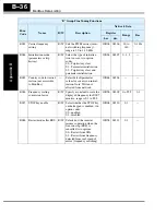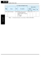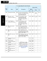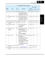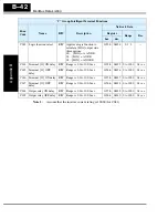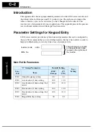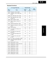
Parameter Settings for Keypad Entry
Appendix C
C–6
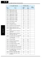
A296
Dec1 to Dec2 frequency transi-
tion point, 2nd motor
0.0
0.0
A097
Acceleration curve selection
00
00
A098
Deceleration curve selection
00
00
A101
[OI]–[L] input active range start
frequency
0.0
0.0
A102
[OI]–[L] input active range end
frequency
0.0
0.0
A103
[OI]–[L] input active range start
current
0.0
0.0
A104
[OI]–[L] input active range end
current
100.
100.
A105
[OI]–[L] input start frequency
enable
01
01
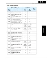
A141
A input select for calculate
function
02
02
A142
B input select for calculate
function
03
03
A143
Calculation symbol
00
00
A145
ADD frequency
0.0
0.0
A146
ADD direction select
00
00
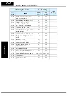
A151
Pot. input active range start
frequency
0.0
0.0
A152
Pot. input active range end
frequency
0.0
0.0
A153
Pot. input active range start
current
0.0
0.0
A154
Pot. input active range end
current
0.0
0.0
A155
Pot. input start frequency enable
01
01
“A” Group Parameters
Default Setting
User
Setting
Func.
Code
Name
-FE(F)
(EU)
-FU
(USA)
Содержание L200-002NFE2
Страница 2: ......
Страница 46: ......
Страница 80: ......
Страница 204: ......
Страница 205: ...Inverter System Accessories In This Chapter page Introduction 2 Component Descriptions 3 Dynamic Braking 5 5 ...
Страница 212: ......
Страница 229: ...Glossary and Bibliography In This Appendix page Glossary 2 Bibliography 8 A ...
Страница 280: ......
Страница 281: ...Drive Parameter Settings Tables In This Appendix page Introduction 2 Parameter Settings for Keypad Entry 2 C ...
Страница 293: ...CE EMC Installation Guidelines In This Appendix page CE EMC Installation Guidelines 2 Hitachi EMC Recommendations 6 D ...
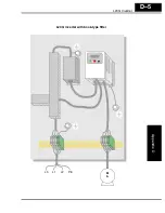
Страница 297: ...L2002 Inverter Appendix D D 5 L1 L2 L3 PE L2002 inverter with book type filter M 3 ...

