L200
2
Inverter
Conf
igur
ing
Dr
iv
e P
a
ra
m
e
ters
3–43
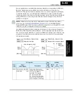
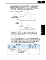
In most applications a controlled deceleration is desirable, corresponding to B091=00.
However, applications such as HVAC fan control will often use a free-run stop
(B091=01). This practice decreases dynamic stress on system components, prolonging
system life. In this case, you will typically set B088=01 in order to resume from the
current speed after a free-run stop (see diagram below, right). Note that using the default
setting, B088=00, can cause trip events when the inverter attempts to force the load
quickly to zero speed.
NOTE:
Other events can cause (or be configured to cause) a free-run stop, such as
“Automatic Restart Mode” on page 3–33
), or an intelligent input
terminal [FRS] signal. If all free-run stop behavior is important to your application (such
as HVAC), be sure to configure each event accordingly.
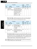
An additional parameter further configures all instances of a free-run stop. Parameter
B003, Retry Wait Time Before Motor Restart, sets the minimum time the inverter will
free-run. For example, if B003 = 4 seconds (and B091=01) and the cause of the free-run-
stop lasts 10 seconds, the inverter will free-run (coast) for a total of 14 seconds before
driving the motor again.
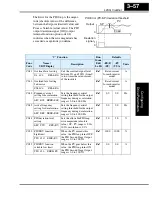
Stop Mode = free-run stop
B091 = 01
B091 = 01
B088 = 00
B088 = 01
[FW, RV]
Motor
speed
t
Resume from 0Hz
Zero-frequency start
t
Stop Mode = free-run stop
Resume from current speed
[FW, RV]
Motor
speed
Wait time
B003
“B” Function
Run
Mode
Edit
Lo Hi
Defaults
Func.
Code
Name /
SRW Display
Description
–FE(F)
(EU)
–FU
(USA)
Units
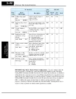
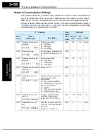
B088 Restart mode after FRS
Selects how the inverter
resumes operation when the
free-run stop (FRS) is
cancelled, two options:
00 .. Restart from 0Hz
01 .. Restart from frequency
detected from real speed of
motor (frequency matching)
✘ ✔
00
00
—
RUN FRS ZST
Содержание L200-002NFE2
Страница 2: ......
Страница 46: ......
Страница 80: ......
Страница 204: ......
Страница 205: ...Inverter System Accessories In This Chapter page Introduction 2 Component Descriptions 3 Dynamic Braking 5 5 ...
Страница 212: ......
Страница 229: ...Glossary and Bibliography In This Appendix page Glossary 2 Bibliography 8 A ...
Страница 280: ......
Страница 281: ...Drive Parameter Settings Tables In This Appendix page Introduction 2 Parameter Settings for Keypad Entry 2 C ...
Страница 293: ...CE EMC Installation Guidelines In This Appendix page CE EMC Installation Guidelines 2 Hitachi EMC Recommendations 6 D ...
Страница 297: ...L2002 Inverter Appendix D D 5 L1 L2 L3 PE L2002 inverter with book type filter M 3 ...

