Using the Front Panel Keypad
In
v
e
rt
er Mounting
and Installation
2–24
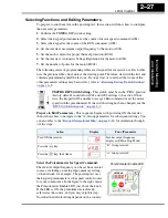
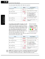
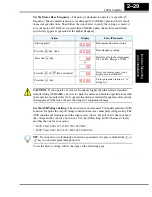
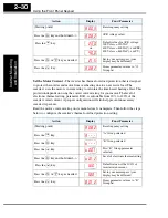
Using the Front Panel Keypad
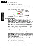
Please take a moment to familiarize yourself with the keypad layout shown in the figure
below. The display is used in programming the inverter’s parameters, as well as monitor-
ing specific parameter values during operation.
Key and Indicator Legend
•
Run/Stop LED
- ON when the inverter output is ON and the motor is developing
torque (Run Mode), and OFF when the inverter output is OFF (Stop Mode).
•
Program/Monitor LED
- This LED is ON when the inverter is ready for parameter
editing (Program Mode). It is OFF when the parameter display is monitoring data
(Monitor Mode).
•
Run Key Enable LED
- is ON when the inverter is ready to respond to the Run key,
OFF when the Run key is disabled.
•
Run Key
- Press this key to run the motor (the Run Enable LED must be ON first).
Parameter F004, Keypad Run Key Routing, determines whether the Run key generates
a Run FWD or Run REV command.
•
Stop/Reset Key
- Press this key to stop the motor when it is running (uses the
programmed deceleration rate). This key will also reset an alarm that has tripped.
•
Potentiometer
- Allows an operator to directly set the motor speed when the potenti-
ometer is enabled for output frequency control.
•
Potentiometer Enable LED
- ON when the potentiometer is enabled for value entry.
•
Parameter Display
- A 4-digit, 7-segment display for parameters and function codes.
•
Display Units, Hertz/Amperes
- One of these LEDs will be ON to indicate the units
associated with the parameter display.
•
Power LED
- This LED is ON when the power input to the inverter is ON.
•
Alarm LED
- ON when an inverter trip is active (alarm relay contacts will be closed).
•
Function Key
- This key is used to navigate through the lists of parameters and
functions for setting and monitoring parameter values.
•
Up/Down (
,
)
Keys
- Use these keys alternately to move up or down the lists of
parameter and functions shown in the display, and increment/decrement values.
•
Store (
)
Key
- When the unit is in Program Mode and you have edited a parameter
value, press the Store key to write the new value to the EEPROM.
1
2
5 0.0
RUN
STOP
RESET
FUNC.
STR
HITACHI
POWER
ALARM
RUN
A
Hz
PRG
Function key
Up/Down keys
Store key
Parameter Display
Run/Stop LED
Program/Monitor LED
Run Key Enable LED
Run Key
Stop/Reset Key
Power LED
Display Units (Hertz / Amperes) LEDs
Potentiometer Enable LED
Potentiometer
Alarm LED
Serial port
1
2
STR
Содержание L200-002NFE2
Страница 2: ......
Страница 46: ......
Страница 80: ......
Страница 204: ......
Страница 205: ...Inverter System Accessories In This Chapter page Introduction 2 Component Descriptions 3 Dynamic Braking 5 5 ...
Страница 212: ......
Страница 229: ...Glossary and Bibliography In This Appendix page Glossary 2 Bibliography 8 A ...
Страница 280: ......
Страница 281: ...Drive Parameter Settings Tables In This Appendix page Introduction 2 Parameter Settings for Keypad Entry 2 C ...
Страница 293: ...CE EMC Installation Guidelines In This Appendix page CE EMC Installation Guidelines 2 Hitachi EMC Recommendations 6 D ...
Страница 297: ...L2002 Inverter Appendix D D 5 L1 L2 L3 PE L2002 inverter with book type filter M 3 ...

