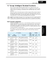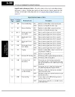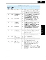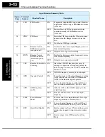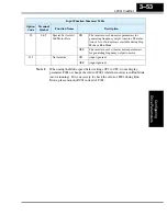
“C” Group: Intelligent Terminal Functions
Configur
ing
Dr
iv
e P
a
ra
m
e
ters
3–52
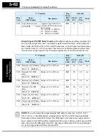
23
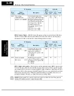
PID
PID Disable
ON
Temporarily disables PID loop control. Inverter
output turns OFF as long as PID Enable is active
(A071=01).
OFF
Has no effect on PID loop operation, which
operates normally if PID Enable is active
(A071=01).
24
PIDC
PID Reset
ON
Resets the PID loop controller. The main conse-
quence is that the integrator sum is forced to
zero.
OFF
No effect on PID loop controller
27
UP
Remote Control
UP Function (motor-
ized speed pot.)
ON
Accelerates (increases output frequency) motor
from current frequency
OFF
Output to motor operates normally
28
DWN
Remote Control
DOWN Function
(motorized speed
pot.)
ON
Decelerates (decreases output frequency) motor
from current frequency
OFF
Output to motor operates normally
29
UDC
Remote Control Data
Clearing
ON
Clears the UP/DWN frequency memory by
forcing it to equal the set frequency parameter
F001. Setting C101 must be set=00 to enable this
function to work.
OFF
UP/DWN frequency memory is not changed
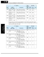
31
OPE
Operator Control
ON
Forces the source of the output frequency setting
(A001) and the source of the RUN command
(A002) to be from the digital operator
OFF
Source of output frequency set by (A001) and
source of run command set by (A002) is used
50
ADD
ADD frequency
enable
ON
Adds the A145 value (Add Frequency) to the
output frequency
OFF
Does not add the A145 value to the output
frequency
51
F-TM
Force Terminal
Mode
ON
Force inverter to use input terminals for output
frequency and Run command sources
OFF
Source of output frequency set by (A001) and
source of Run command set by (A002) is used
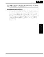
52
RDY
Quick Start Enable
ON
Inverter output is always ON (even when motor
rotation has stopped) to improve motor startup
time.
OFF
Inverter output turns OFF normally in Stop
Mode.
Input Function Summary Table
Option
Code
Terminal
Symbol
Function Name
Description
Содержание L200-002NFE2
Страница 2: ......
Страница 46: ......
Страница 80: ......
Страница 204: ......
Страница 205: ...Inverter System Accessories In This Chapter page Introduction 2 Component Descriptions 3 Dynamic Braking 5 5 ...
Страница 212: ......
Страница 229: ...Glossary and Bibliography In This Appendix page Glossary 2 Bibliography 8 A ...
Страница 280: ......
Страница 281: ...Drive Parameter Settings Tables In This Appendix page Introduction 2 Parameter Settings for Keypad Entry 2 C ...
Страница 293: ...CE EMC Installation Guidelines In This Appendix page CE EMC Installation Guidelines 2 Hitachi EMC Recommendations 6 D ...
Страница 297: ...L2002 Inverter Appendix D D 5 L1 L2 L3 PE L2002 inverter with book type filter M 3 ...

