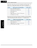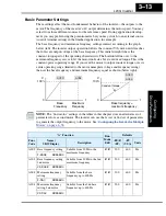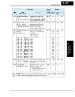
“A” Group: Standard Functions
Configur
ing
Dr
iv
e P
a
ra
m
e
ters
3–18
Torque Control Algorithms
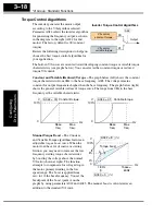
The inverter generates the motor output
according to the V/f algorithm selected.
Parameter A044 selects the inverter algorithm
for generating the frequency output, as shown
in the diagram to the right (A244 for 2nd
motor). The factory default is 00 (constant
torque).
Review the following descriptions to help you
choose the best torque control algorithm for
your application.
The built-in V/f curves are oriented toward developing constant torque or variable torque
characteristics (see graphs below). You can select either constant torque or reduced
torque V/f control.
Constant and Variable (Reduced) Torque –
The graph below (left) shows the constant
torque characteristic from 0Hz to the base frequency A003. The voltage remains
constant for output frequencies higher than the base frequency. The graph below (right)
shows the general variable (reduced) torque curve. The range from 0Hz to the base
frequency is the variable characteristic.
Manual Torque Boost –
The Constant
and Variable Torque algorithms feature an
adjustable
torque boost
curve. When the
motor load has a lot of inertia or starting
friction, you may need to increase the low
frequency starting torque characteristics
by boosting the voltage above the normal
V/f ratio (shown at right). The function
attempts to compensate for voltage drop in
the motor primary winding in the low
speed range. The boost is applied from
zero to 1/2 the base frequency. You set the
breakpoint of the boost (point A on the
graph) by using parameters A042 and A043. The manual boost is calculated as an
addition to the standard V/f curve.
Output
A44
V/f control,
constant torque
V/f control,
variable torque
00
01
Inverter Torque Control Algorithms
Constant torque
A044 = 00
V
100%
Hz
0
Variable torque
A044 = 01
V
100%
Hz
0
Base
freq.
Max.
freq.
Base
freq.
Max.
freq.
f base =
60Hz
Torque boost
A042 = 8
A043 = 3
(%)
V
Hz
100%
8%
1.8Hz
A
0
(%)
3%
Содержание L200-002NFE2
Страница 2: ......
Страница 46: ......
Страница 80: ......
Страница 204: ......
Страница 205: ...Inverter System Accessories In This Chapter page Introduction 2 Component Descriptions 3 Dynamic Braking 5 5 ...
Страница 212: ......
Страница 229: ...Glossary and Bibliography In This Appendix page Glossary 2 Bibliography 8 A ...
Страница 280: ......
Страница 281: ...Drive Parameter Settings Tables In This Appendix page Introduction 2 Parameter Settings for Keypad Entry 2 C ...
Страница 293: ...CE EMC Installation Guidelines In This Appendix page CE EMC Installation Guidelines 2 Hitachi EMC Recommendations 6 D ...
Страница 297: ...L2002 Inverter Appendix D D 5 L1 L2 L3 PE L2002 inverter with book type filter M 3 ...


