L200
2
Inverter
T
roub
leshooting
and Maintenance
6–15
IGBT Test Method
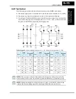
The following procedure will check the inverter transistors (IGBTs) and diodes:
1.
Disconnect input power to terminals [R, S, and T] and motor terminals [U, V, and W].
2.
Disconnect any wires from terminals [+] and [–] for regenerative braking.
3.
Use a Digital Volt Meter (DVM) and set it for 1
Ω
resistance range. You can check the
status of the charging state of terminals [R, S, T, U, V, W, +, and –] of the inverter and
the probe of the DVM by measuring the charging state.
Table Legend –
Almost infinite resistance:
≅
∞
Ω
Almost zero resistance:
≅ 0 Ω
NOTE:
The resistance values for the diodes or the transistors will not be exactly the
same, but they will be close. If you find a significant difference, a problem may exist.
NOTE:
Before measuring the voltage between [+] and [–] with the DC current range,
confirm that the smoothing capacitor is discharged fully, then execute the tests.
Part
DVM
Measured
Value
Part
DVM
Measured
Value
Part
DVM
Measured
Value
+
–
+
–
+
–
D1
[R]
+1
≅ ∞ Ω
D5
[S]
[N]
≅
0
Ω
TR3
[W]
[+]
≅ ∞ Ω
+1
[R]
≅
0
Ω
[N]
[S]
≅ ∞ Ω
[+]
[W]
≅
0
Ω
D2
[S]
+1
≅ ∞ Ω
D6
[T]
[N]
≅
0
Ω
TR4
[U]
[–]
≅
0
Ω
+1
[S]
≅
0
Ω
[N]
[T]
≅ ∞ Ω
[–]
[U]
≅ ∞ Ω
D3
[T]
+1
≅ ∞ Ω
TR1
[U]
[+]
≅ ∞ Ω
TR5
[V]
[–]
≅
0
Ω
+1
[T]
≅
0
Ω
[+]
[U]
≅
0
Ω
[–]
[V]
≅ ∞ Ω
D4
[R]
[N]
≅
0
Ω
TR2
[V]
[+]
≅ ∞ Ω
TR6
[W]
[–]
≅
0
Ω
[N]
[R]
≅ ∞ Ω
[+]
[V]
≅
0
Ω
[–]
[W]
≅ ∞ Ω
[R]
[S]
[T]
TR1
TR2
TR3
[U]
[V]
[W]
[–]
D1
D2
D3
D4
D5
D6
+
[+]
[+1]
TR4
TR5
TR6
Содержание L200-002NFE2
Страница 2: ......
Страница 46: ......
Страница 80: ......
Страница 204: ......
Страница 205: ...Inverter System Accessories In This Chapter page Introduction 2 Component Descriptions 3 Dynamic Braking 5 5 ...
Страница 212: ......
Страница 229: ...Glossary and Bibliography In This Appendix page Glossary 2 Bibliography 8 A ...
Страница 280: ......
Страница 281: ...Drive Parameter Settings Tables In This Appendix page Introduction 2 Parameter Settings for Keypad Entry 2 C ...
Страница 293: ...CE EMC Installation Guidelines In This Appendix page CE EMC Installation Guidelines 2 Hitachi EMC Recommendations 6 D ...
Страница 297: ...L2002 Inverter Appendix D D 5 L1 L2 L3 PE L2002 inverter with book type filter M 3 ...

