“A” Group: Standard Functions
Configur
ing
Dr
iv
e P
a
ra
m
e
ters
3–12
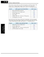
The inverter has other control sources that can temporarily override the parameter A001
setting, forcing a different output frequency source. The following table lists all
frequency source setting methods and their relative priority (“1” is the highest priority).
The inverter also has other control sources that can temporarily override the parameter
A002 setting, forcing a different Run command source. The following table lists all Run
command setting methods and their relative priority (“1” is the highest priority).
Priority
A001 Frequency Source Setting Method
Refer to page...
1
[CF1] to [CF4] Multi-speed terminals
2
[OPE] Operator Control intelligent input
3
[F-TM] intelligent input
4
[AT] terminal
5
TM/PRG DIP Switch - (if switch is in “TM” position)
6
A001 Frequency source setting
Priority
A002 Run Command Setting Method
Refer to page...
1
[OPE] Operator Control intelligent input
2
[F-TM] intelligent input
3
TM/PRG DIP Switch - (if switch is in “TM” position)
4
A002 Run command source setting
Содержание L200-002NFE2
Страница 2: ......
Страница 46: ......
Страница 80: ......
Страница 204: ......
Страница 205: ...Inverter System Accessories In This Chapter page Introduction 2 Component Descriptions 3 Dynamic Braking 5 5 ...
Страница 212: ......
Страница 229: ...Glossary and Bibliography In This Appendix page Glossary 2 Bibliography 8 A ...
Страница 280: ......
Страница 281: ...Drive Parameter Settings Tables In This Appendix page Introduction 2 Parameter Settings for Keypad Entry 2 C ...
Страница 293: ...CE EMC Installation Guidelines In This Appendix page CE EMC Installation Guidelines 2 Hitachi EMC Recommendations 6 D ...
Страница 297: ...L2002 Inverter Appendix D D 5 L1 L2 L3 PE L2002 inverter with book type filter M 3 ...

