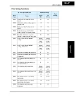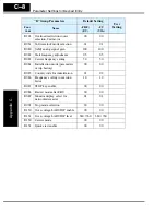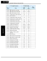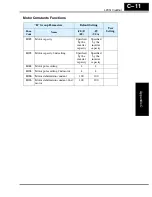
L200
2
Inverter
Appendix D
D–3
4.
Take measures to minimize interference that is frequently coupled in through installa-
tion cables.
• Separate interfering cables with 0.25m minimum from cables susceptible to inter-
ference. A particularly critical point is laying parallel cables over longer distances.
If two cables intersect (one crosses over the other), the interference is smallest if
they intersect at an angle of 90°. Cables susceptible to interference should there-
fore only intersect motor cables, intermediate circuit cables, or the wiring of a
rheostat at right angles and never be laid parallel to them over longer distances.
5.
Minimize the distance between an interference source and an interference sink (inter-
ference-threatened device), thereby decreasing the effect of the emitted interference
on the interference sink.
• You should use only interference-free devices and maintain a minimum distance
of 0.25 m from the adjustable frequency inverter.
6.
Follow safety measures in the filter installation.
• Ensure that the ground terminal (PE) of the filter is properly connected to the
ground terminal of the adjustable frequency inverter. An HF ground connection
via metal contact between the housings of the filter and the adjustable frequency
inverter, or solely via cable shield, is not permitted as a protective conductor
connection. The filter must be solidly and permanently connected with the ground
potential so as to preclude the danger of electric shock upon touching the filter if a
fault occurs.
To achieve a protective ground connection for the filter:
• Ground the filter with a conductor of at least 10 mm
2
cross-sectional area.
• Connect a second grounding conductor, using a separate grounding terminal
parallel to the protective conductor. (The cross section of each single protective
conductor terminal must be sized for the required nominal load.)
Содержание L200-002NFE2
Страница 2: ......
Страница 46: ......
Страница 80: ......
Страница 204: ......
Страница 205: ...Inverter System Accessories In This Chapter page Introduction 2 Component Descriptions 3 Dynamic Braking 5 5 ...
Страница 212: ......
Страница 229: ...Glossary and Bibliography In This Appendix page Glossary 2 Bibliography 8 A ...
Страница 280: ......
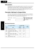
Страница 281: ...Drive Parameter Settings Tables In This Appendix page Introduction 2 Parameter Settings for Keypad Entry 2 C ...
Страница 293: ...CE EMC Installation Guidelines In This Appendix page CE EMC Installation Guidelines 2 Hitachi EMC Recommendations 6 D ...
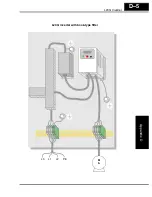
Страница 297: ...L2002 Inverter Appendix D D 5 L1 L2 L3 PE L2002 inverter with book type filter M 3 ...

