Using Intelligent Output Terminals
Oper
ations
and Monitor
ing
4–52
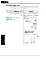
Option Card Detection Signal
The expansion card provides a CANopen network interface for the inverter. When the
card is installed, you can configure an intelligent input to indicate the network status.
The watchdog timer value is set by parameter P044.
Option
Code
Terminal
Symbol
Function Name
Output
State
Description
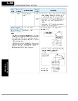
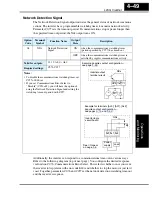
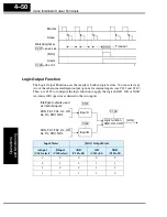
10
ODc
Option Card Detec-
tion Signal
ON
when the network is detected and operating
normally
OFF
when the network is not detected or not operat-
ing normally
Valid for outputs:
11, 12, AL0 – AL2
Required settings:
P044
Notes:
RY
+
–
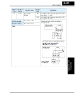
Example (requires output configuration—
see page
):
Inverter output
terminal circuit
ODc
12 11
CM2
Example for terminals [AL0], [AL1], [AL2]
(requires output configuration—
see pages
):
AL0
AL2
AL1
Inverter logic
circuit board
See I/O specs
on page
.
ODc
Load
Power
supply
Содержание L200-002NFE2
Страница 2: ......
Страница 46: ......
Страница 80: ......
Страница 204: ......
Страница 205: ...Inverter System Accessories In This Chapter page Introduction 2 Component Descriptions 3 Dynamic Braking 5 5 ...
Страница 212: ......
Страница 229: ...Glossary and Bibliography In This Appendix page Glossary 2 Bibliography 8 A ...
Страница 280: ......
Страница 281: ...Drive Parameter Settings Tables In This Appendix page Introduction 2 Parameter Settings for Keypad Entry 2 C ...
Страница 293: ...CE EMC Installation Guidelines In This Appendix page CE EMC Installation Guidelines 2 Hitachi EMC Recommendations 6 D ...
Страница 297: ...L2002 Inverter Appendix D D 5 L1 L2 L3 PE L2002 inverter with book type filter M 3 ...


