“A” Group: Standard Functions
Configur
ing
Dr
iv
e P
a
ra
m
e
ters
3–16
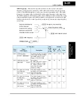
The example graph below shows a typical analog input waveform. The filter removes the
noise spikes. When a speed change (such as level increase) occurs, the filter naturally
has a delayed response. Due to the deadband feature (A016=17), the final output
changes only when the 16-sample average moves past the deadband threshold.
TIP:
The deadband feature is useful in applications that require a very stable output
frequency but use an analog input for the speed reference. Example application: A
grinding machine uses a remote potentiometer for operator speed input. After a setting
change, the grinder maintains a very stable speed to deliver a uniform finished surface.
Multi-speed and Jog Frequency Setting
The L200
2
inverter has the capability to store and output up to 16 preset frequencies to
the motor (A020 to A035). As in traditional motion terminology, we call this
multi-speed
profile
capability. These preset frequencies are selected by means of digital inputs to the
inverter. The inverter applies the current acceleration or deceleration setting to change
from the current output frequency to the new one. The first multi-speed setting is dupli-
cated for the second motor settings (the remaining 15 multi-speeds apply only to the first
motor).
The jog speed setting is used whenever the Jog command is active. The jog speed setting
range is arbitrarily limited to 10 Hz, to provide safety during manual operation. The
acceleration to the jog frequency is instantaneous, but you can choose from three modes
for the best method for stopping the jog operation.
Hz
t
“0”
Deadband
A016=17
noise spikes
16-sample avg.
+0.1
Output freq.
reference
Analog input
New deadband
speed increase given
–0.2
Threshold exceeded
+0.1
“0”
–0.2
Small step-change
Содержание L200-002NFE2
Страница 2: ......
Страница 46: ......
Страница 80: ......
Страница 204: ......
Страница 205: ...Inverter System Accessories In This Chapter page Introduction 2 Component Descriptions 3 Dynamic Braking 5 5 ...
Страница 212: ......
Страница 229: ...Glossary and Bibliography In This Appendix page Glossary 2 Bibliography 8 A ...
Страница 280: ......
Страница 281: ...Drive Parameter Settings Tables In This Appendix page Introduction 2 Parameter Settings for Keypad Entry 2 C ...
Страница 293: ...CE EMC Installation Guidelines In This Appendix page CE EMC Installation Guidelines 2 Hitachi EMC Recommendations 6 D ...
Страница 297: ...L2002 Inverter Appendix D D 5 L1 L2 L3 PE L2002 inverter with book type filter M 3 ...


