L200
2
Inverter
T
roub
leshooting
and Maintenance
6–13
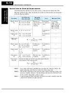
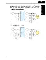
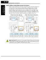
The figures below show measurement locations for voltage, current, and power measure-
ments listed in the table on the previous page. The voltage to be measured is the funda-
mental wave effective voltage. The power to be measured is the total effective power.
E
1
W
1
I
1
I
1
I
1
I
1
E
U-V
E
U-V
E
U-V
W
01
W
02
E
1
I
1
I
1
I
1
I
1
E
U-V
E
U-V
E
U-V
W
01
W
02
W
01
W
02
E
1
E
1
I
2
I
3
Single-phase Measurement Diagram
Three-phase Measurement Diagram
L1
N
L1
N
U
V
W
T1
T2
T3
Inverter
Motor
T1
T2
T3
U
V
W
R
S
T
Inverter
Motor
L1
L2
L3
Содержание L200-002NFE2
Страница 2: ......
Страница 46: ......
Страница 80: ......
Страница 204: ......
Страница 205: ...Inverter System Accessories In This Chapter page Introduction 2 Component Descriptions 3 Dynamic Braking 5 5 ...
Страница 212: ......
Страница 229: ...Glossary and Bibliography In This Appendix page Glossary 2 Bibliography 8 A ...
Страница 280: ......
Страница 281: ...Drive Parameter Settings Tables In This Appendix page Introduction 2 Parameter Settings for Keypad Entry 2 C ...
Страница 293: ...CE EMC Installation Guidelines In This Appendix page CE EMC Installation Guidelines 2 Hitachi EMC Recommendations 6 D ...
Страница 297: ...L2002 Inverter Appendix D D 5 L1 L2 L3 PE L2002 inverter with book type filter M 3 ...

