xii
CAUTION:
When the EEPROM error E08 occurs, be sure to confirm the setting values
again.
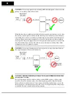
CAUTION:
When using
normally closed
active state settings (C011 to C015) for exter-
nally commanded Forward or Reverse terminals [FW] or [RV], the inverter may start
automatically
when the external system is powered OFF or disconnected from the
inverter!
So, do not use normally closed active state settings for Forward or Reverse
terminals [FW] or [RV] unless your system design protects against unintended motor
operation.
CAUTION:
In all the illustrations in this manual, covers and safety devices are
occasionally removed to describe the details. While operating the product, make sure
that the covers and safety devices are placed as they were specified originally and
operate it according to the instruction manual.
UL
®
Cautions, Warnings, and Instructions
Wiring Warnings for Electrical Practices and Wire Sizes
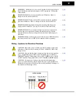
The Warnings and instructions in this section summarize the procedures necessary to
ensure an inverter installation complies with Underwriters Laboratories
®
guidelines.
WARNING:
“Use 60/75°C Cu wire only” or equivalent.
WARNING:
“Open Type Equipment.”
WARNING:
“Suitable for use on a circuit capable of delivering not more than 100,000
rms symmetrical amperes, 240 V maximum.” For models with suffix N or L.
WARNING:
“Suitable for use on a circuit capable of delivering not more than 100,000
rms symmetrical amperes, 480 V maximum.” For models with suffix H.
WARNING:
“Hot surface—risk of burn.”
WARNING:
“Install device in pollution degree 2 environment.”
WARNING:
“Maximum Surrounding Air Temperature 50°C” or equivalent.
WARNING:
“Risk of electric shock—capacitor discharge time is at least 5 minutes.”
WARNING:
“Solid state motor overload protection is provided in each model.”
WARNING:
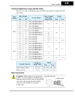
“Tightening torque and wire range for field wiring terminals are marked
adjacent to the terminal or on the wiring diagram.”
Содержание L200-002NFE2
Страница 2: ......
Страница 46: ......
Страница 80: ......
Страница 204: ......
Страница 205: ...Inverter System Accessories In This Chapter page Introduction 2 Component Descriptions 3 Dynamic Braking 5 5 ...
Страница 212: ......
Страница 229: ...Glossary and Bibliography In This Appendix page Glossary 2 Bibliography 8 A ...
Страница 280: ......
Страница 281: ...Drive Parameter Settings Tables In This Appendix page Introduction 2 Parameter Settings for Keypad Entry 2 C ...
Страница 293: ...CE EMC Installation Guidelines In This Appendix page CE EMC Installation Guidelines 2 Hitachi EMC Recommendations 6 D ...
Страница 297: ...L2002 Inverter Appendix D D 5 L1 L2 L3 PE L2002 inverter with book type filter M 3 ...

