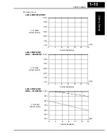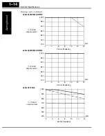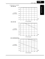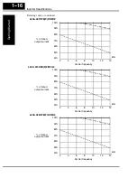
L200
2
Inverter
Getting Star
ted
1–11
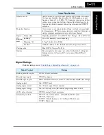
Signal Ratings
Detailed ratings are in
“Control Logic Signal Specifications” on page 4–6
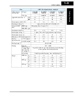
Other functions
AVR function, curved accel/decel profile, upper and lower limiters,
16-stage speed profile, fine adjustment of start frequency, carrier
frequency change (2 to 14 kHz) *10, frequency jump, gain and bias
setting, process jogging, electronic thermal level adjustment, retry
function, trip history monitor, 2nd setting selection, fan ON/OFF
selection
Protective function
Over-current, over-voltage, under-voltage, overload, extreme high/
low temperature, CPU error, memory error, ground fault detection at
startup, internal communication error, electronic thermal
Operat-
ing
Environ
ment
Temperature
Operating (ambient): -10 to 40
°
C (*10) / Storage: -25 to 60
°
C (*11)
Humidity
20 to 90% humidity (non-condensing)
Vibration *12
5.9 m/s
2
(0.6G), 10 to 55 Hz
Location
Altitude 1,000 m or less, indoors (no corrosive gasses or dust)
Coating color
Blue (DIC 14 Version No. 436)
Options
Remote operator unit, copy unit, cables for the units, braking unit,
braking resistor, AC reactor, DC reactor, noise filter, DIN rail
mounting
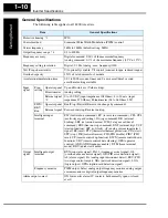
Item
General Specifications
Signal / Contact
Ratings
Built-in power for inputs
24VDC, 30 mA maximum
Discrete logic inputs
27VDC maximum
Discrete logic outputs
50mA maximum ON state current, 27 VDC maximum OFF state voltage
Analog output
0 to 10VDC, 1 mA
Analog input, current
4 to 19.6 mA range, 20 mA nominal
Analog input, voltage
0 to 9.6 VDC range, 10VDC nominal, input impedance 10 k
Ω
+10V analog reference
10VDC nominal, 10 mA maximum
Alarm relay contacts
250 VAC, 2.5A (R load) max., 0.2A (I load, P.F.=0.4) max.
100 VAC, 10mA min.
30 VDC, 3.0A (R load) max., 0.7A (I load, P.F.=0.4) max.
5 VDC, 100mA min.
Содержание L200-002NFE2
Страница 2: ......
Страница 46: ......
Страница 80: ......
Страница 204: ......
Страница 205: ...Inverter System Accessories In This Chapter page Introduction 2 Component Descriptions 3 Dynamic Braking 5 5 ...
Страница 212: ......
Страница 229: ...Glossary and Bibliography In This Appendix page Glossary 2 Bibliography 8 A ...
Страница 280: ......
Страница 281: ...Drive Parameter Settings Tables In This Appendix page Introduction 2 Parameter Settings for Keypad Entry 2 C ...
Страница 293: ...CE EMC Installation Guidelines In This Appendix page CE EMC Installation Guidelines 2 Hitachi EMC Recommendations 6 D ...
Страница 297: ...L2002 Inverter Appendix D D 5 L1 L2 L3 PE L2002 inverter with book type filter M 3 ...


