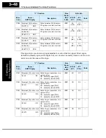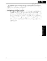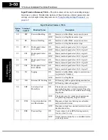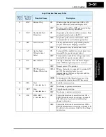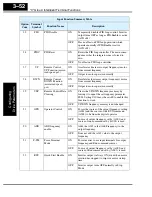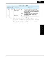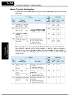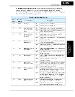
“C” Group: Intelligent Terminal Functions
Configur
ing
Dr
iv
e P
a
ra
m
e
ters
3–62
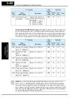
Output Signal ON/OFF Delay Function -
Intelligent outputs including terminals [11],
[12], and the output relay, have configurable signal transition delays. Each output can
delay either the OFF-to-ON or ON-to-OFF transitions, or both. Signal transition delays
are variable from 0.1 to 100.0 seconds. This feature is useful in applications that must
tailor inverter output signals to meet timing requirements of certain external devices.
NOTE:
If you are using the output terminal OFF delay feature (any of C145, C147,
C149 > 0.0 sec.), the [RS] (Reset) terminal affects the ON-to-OFF transition slightly.
Normally (without using OFF delays), the [RS] input causes the motor output and the
logic outputs to turn OFF together, immediately. However, when any output uses an OFF
delay, then after the [RS] input turns ON, that output will remain ON for an additional 1
sec. period (approximate) before turning OFF.
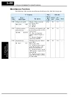
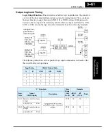
C143 Logic function select
Applies a logic function to
calculate [LOG] output state,
three options:
00... [LOG] = A AND B
01... [LOG] = A OR B
02... [LOG] = A XOR B
✘ ✘
00
00
—
LogicOPE AND
“C” Function
Run
Mode
Edit
Lo Hi
Defaults
Func.
Code
Name /
SRW Display
Description
–FE(F)
(EU)
–FU
(USA)
Units
“C” Function
Run
Mode
Edit
Lo Hi
Defaults
Func.
Code
Name /
SRW Display
Description
–FE(F)
(EU)
–FU
(USA)
Units
C144 Terminal [11] ON delay Range is 0.0 to 100.0 sec.
✘ ✔
0.0
0.0
sec.
DLAY 11 0000.0s
C145 Terminal [11] OFF
delay
Range is 0.0 to 100.0 sec.
✘ ✔
0.0
0.0
sec.
HOLD 11 0000.0s
C146 Terminal [12] ON delay Range is 0.0 to 100.0 sec.
✘ ✔
0.0
0.0
sec.
DLAY 12 0000.0s
C147 Terminal [12] OFF
delay
Range is 0.0 to 100.0 sec.
✘ ✔
0.0
0.0
sec.
HOLD 12 0000.0s
C148 Output relay ON delay
Range is 0.0 to 100.0 sec.
✘ ✔
0.0
0.0
sec.
DLAY RY 0000.0s
C149 Output relay OFF delay
Range is 0.0 to 100.0 sec.
✘ ✔
0.0
0.0
sec.
HOLD RY 0000.0s
Содержание L200-002NFE2
Страница 2: ......
Страница 46: ......
Страница 80: ......
Страница 204: ......
Страница 205: ...Inverter System Accessories In This Chapter page Introduction 2 Component Descriptions 3 Dynamic Braking 5 5 ...
Страница 212: ......
Страница 229: ...Glossary and Bibliography In This Appendix page Glossary 2 Bibliography 8 A ...
Страница 280: ......
Страница 281: ...Drive Parameter Settings Tables In This Appendix page Introduction 2 Parameter Settings for Keypad Entry 2 C ...
Страница 293: ...CE EMC Installation Guidelines In This Appendix page CE EMC Installation Guidelines 2 Hitachi EMC Recommendations 6 D ...
Страница 297: ...L2002 Inverter Appendix D D 5 L1 L2 L3 PE L2002 inverter with book type filter M 3 ...

