“B” Group: Fine Tuning Functions
Configur
ing
Dr
iv
e P
a
ra
m
e
ters
3–44
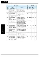
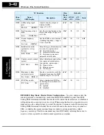
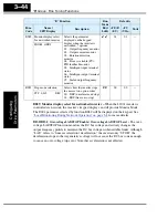
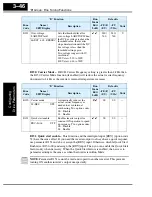
B089: Monitor display select for networked inverter –
When the L200
2
inverter is
controlled via network, the inverter’s keypad display can still provide Monitor Mode.
The D00x parameter selected by function B089 will be displayed on the keypad. See
“Local Monitoring During Network Operation” on page 3–8
for more details.
B130/B131:
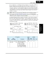
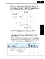
Over-voltage LADSTOP Enable / Over-voltage LADSTOP Level –
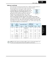
The over-
voltage LADSTOP function monitors the DC bus voltage and actively changes the
output frequency profile to maintain the DC bus voltage within settable limits. Although
“LAD” refers to “linear acceleration / deceleration,” the inverter only “STOPs” the
deceleration slope so that regenerative voltage will not cause the DC bus to rise enough
to cause an over-voltage trip event. Note that acceleration is not affected.
B089 Monitor display select
for networked inverter
Selects the parameter
displayed on the keypad
display when the inverter is
networked, 7 options:
01... Output frequency monitor
02... Output current monitor
03... Rotation direction
monitor
04... Process variable (PV),
PID feedback monitor
05... Intelligent input terminal
status
06... Intelligent output terminal
status
07... Scaled output frequency
monitor
✔ ✔
01
01
—
PANEL d001
B091 Stop mode selection
Selects how the inverter stops
the motor, two option codes:
00... DEC (decelerate and stop)
01... FRS (free run to stop)
✘ ✘
00
00
—
STP Slct DEC
“B” Function
Run
Mode
Edit
Lo Hi
Defaults
Func.
Code
Name /
SRW Display
Description
–FE(F)
(EU)
–FU
(USA)
Units
Содержание L200-002NFE2
Страница 2: ......
Страница 46: ......
Страница 80: ......
Страница 204: ......
Страница 205: ...Inverter System Accessories In This Chapter page Introduction 2 Component Descriptions 3 Dynamic Braking 5 5 ...
Страница 212: ......
Страница 229: ...Glossary and Bibliography In This Appendix page Glossary 2 Bibliography 8 A ...
Страница 280: ......
Страница 281: ...Drive Parameter Settings Tables In This Appendix page Introduction 2 Parameter Settings for Keypad Entry 2 C ...
Страница 293: ...CE EMC Installation Guidelines In This Appendix page CE EMC Installation Guidelines 2 Hitachi EMC Recommendations 6 D ...
Страница 297: ...L2002 Inverter Appendix D D 5 L1 L2 L3 PE L2002 inverter with book type filter M 3 ...

