


7.1 Safety Loops
66
7.
INTERFACES
ERS systems can be equipped with one or more interfaces.
CAN-Bus interface for remote control
CAN-Gateway: Remote-control with different communication protocols
Interlock loop for secure shutdown of the outputs
Channel stop for shutdown of single channels
Sense-connection
Safety Loops
Interlock
This is a device safety shutdown that immediately switches off both outputs; it is activated by open-
ing a potential-free contact between pin 1/2 or 3/4 of terminal -X4.1. This safety shutdown is effective
independent of all other switch positions and device settings (also independent of the settings from
the digital interface).
Normal device operation is only possible if the interlock function is deactivated by a connection be-
tween the terminals of the interlock interface by the test bench emergency loop.
Additionally the current status of the interlock is output via a potential free contact at pins 5 and 6
Table 35 Pin assignment -X4.1 Interlock
Signal
Pin -X4.1
Description
ILOCK-ext
1
Interlock 1
Loop closed = OK
ILOCK-ext
2
ILOCK-ext-2
3
Interlock 2
Loop closed = OK
ILOCK-ext-2
4
FB_ILOCK
5
Feedback Interlock
Potential free contact, open = OK
FB_ILOCK
6
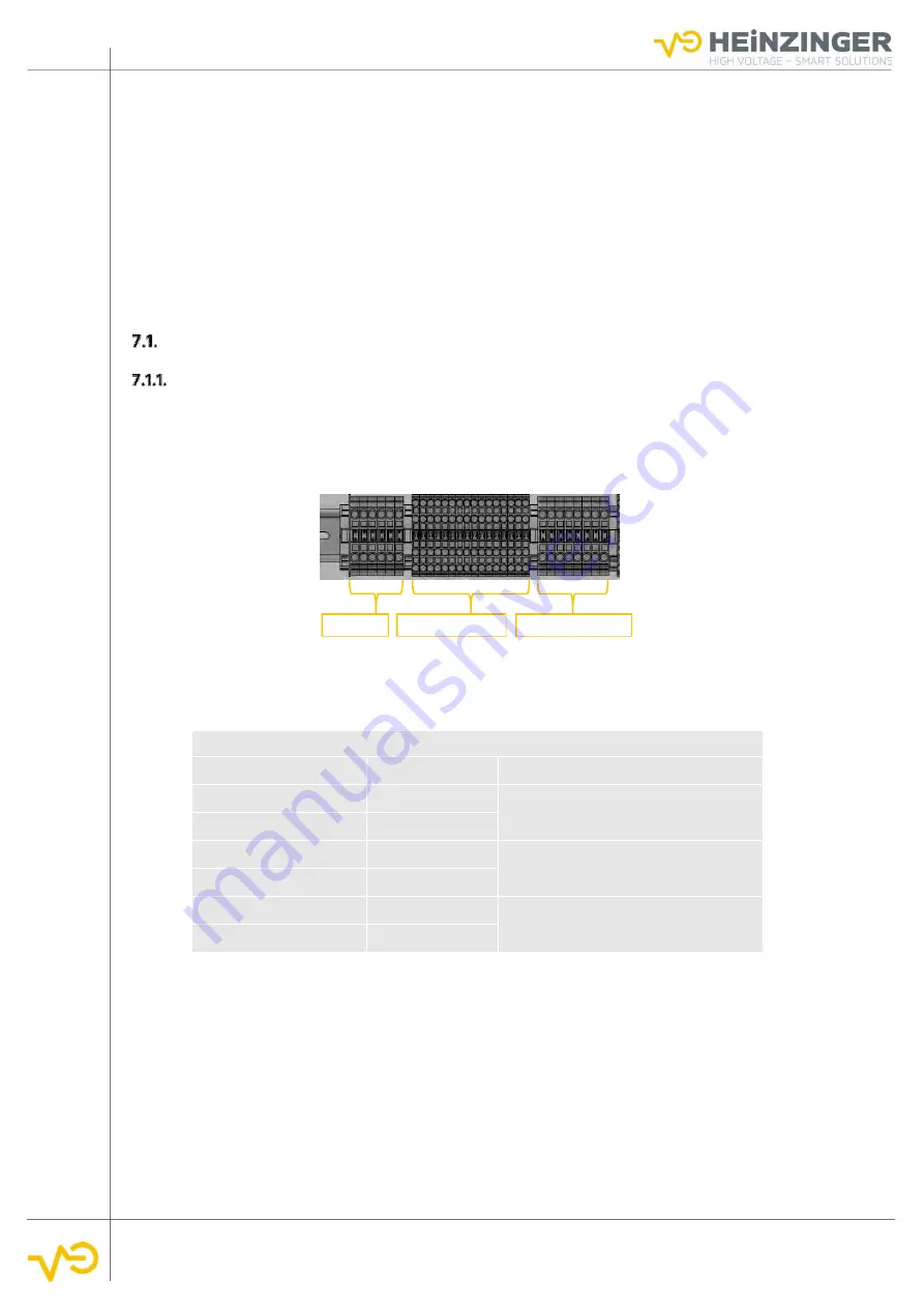
Fig. 61 Terminal strip -X4
-X4.1
-X4.2(optional)
-X4.3(optional)