3B3-8 POWER STEERING COMPONENTS - TRW ROSS
rack pistoh. Repeauhis procedure for the other
-
poppet adjuster seat and sleeve assembly.
• If one poppet adjuster seat and sleeve
assembly was left in the rack piston, it can
be reset for automatic poppet adjustment by
inserting a 9.52 mm by 152 mm (3/8 inch by
6 inch) drill rod down through the poppet
seat hole at the opposite end of the rack
piston. Press the adjuster seat in until it bot
toms against the adjuster sleeve,
NOTICE: Do not allow thread locking com
pounds to get on the adjuster seat compo
n e n t o f the a d ju s te r s e a t a n d s le e v e
assembly or the adjustment function of this
assembly will be adversely affected.
• Apply Loctite T primer or equivalent to the
threaded poppet holes in the rack piston and to
the threads on the adjuster seat and sleeve
assemblies. Allow it to dry for ten minutes. !
• Apply Loctite RC680 or equivalent to these
threads.;
CAUTION: Wear eye protection while assem
bling poppets. Spring loaded poppets could
eject and cause personal injury.
• Place the rack piston in a soft jawed vise and
turn a poppet adjuster seat and sleeve assem-
v;
bly into one poppet hole.(slotted end out).
•From the other end, install one poppet (23),
poppet spring (24), spacer rod (25), push tube
(26), other poppet (23), and the other adjuster
seat and sleeve assembly (22).
;
Tighten
!
• Poppet adjuster seat and sleeve assemblies to
13 N-m (120 in. lbs.) using J 36452.
i
• Place the rack pistoh with the ball guide holes fac:
ing up on a pedestal that will raise the rack piston
worm bore high enough to assemble the worm encj
of the input shaft.
j
10. New back up seal (21), followed by a new seal (20)
on the rack piston.
]
• Do not over stretch these rings.
j
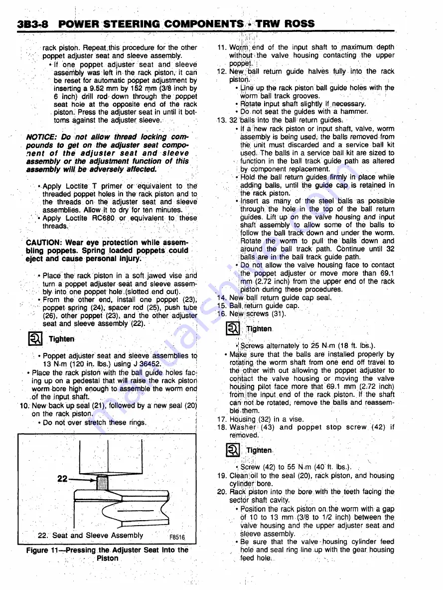
22. Seat and Sleeve Assembly
F8516
Figure 11 —Pressing the Adjuster Seat Into the
. Piston .
11. Wqijrrv end of the input shaft to maximum depth
without the valve housing contacting the upper
■
poppet. ;
12. New; ball return guide halves fully into the rack
:
pistOri.''
■
!■
• Line up the rack piston ball guide holes with the
worm ball track grooves.
• Rotate input shaft slightly if necessary.
• Do not seat the guides with a hammer.
13. 32 balls into the ball return guides.
• If a new rack piston or input shaft, valve, worm
assembly is being used, the balls removed from
the unit must discarded and a service ball kit
usedi The balls in a service ball kit are sized to
- function in the ball track guide path as altered
i by component replacement.
• Hold the ball return guides firmly in place while
adding balls, until the guide cap is retained in
the rack piston.
• Insert as many of the steel balls as possible
through the hole in the top of the ball return
guides. Lift up on the valve housing and input
shaft assembly to allow some of the balls to
follow the ball track down and under the worm.
Rotate the worm to pull the balls down and
around the ball track path. Continue until 32
balls are in the ball track guide path.
• bp not allow the valve housing face to contact
the poppet adjuster or move more than 69.1
mm (2.72 inch) from the upper end of the rack
pistoh during these procedures.
14. New ball return guide cap seal,
15. Ball, ripturn guide cap.
16. Ne|vyiscrews (31).
Q Tighten
•j Screws alternately to 25 N-m (18 ft. lbs.).
• Make sure that the balls are installed properly by
rotating the worm shaft from one end off travel to
the other with out allowing the poppet adjuster to
contact the valve housing or moving the valve
housing pilot face more that 69.1 mm (2.72 inch)
from;the input end of the rack piston. If the shaft
can pot ,be rotated, remove the balls and reassem
bly them.
17- Housing (32) in a vise.
i
18. Washer (43) and poppet stop screw (42) if
removed.
£
Tighten
•; Screw (42) to 55 N m (40 ft. lbs.).
19. Clean oil to the seal (20), rack piston, and housing
cylinder bore.
20. Rack piston into the bore, with the teeth facing the
sector shaft cavity.
• Position the rack piston on the worm with a gap
,
of 10 to 13 mm (3/8 to 1/2 inch) between the.
valve housing and the upper adjuster seat and
sleeve assembly.
• Be sure that the valve .housing cylinder feed
hole and seal ring line up with the gear housing
feed hole: ,
Содержание C Series 1993
Страница 1: ......
Страница 12: ...OA 6 GENERAL INFORMATION Figure 11 Allison Transmission I D Location ...
Страница 44: ...3B1A 2 POWER STEERING GEAR UNIT REPAIR Figure 1 710 Power Steering Gear ...
Страница 62: ......
Страница 75: ...3B3 2 POWER STEERING COMPONENTS TRW ROSS ...
Страница 101: ...5P2 4 HYDRAULIC BOOSTER Figure 5 Removing the Seal Plug Figure 3 Removing the End Cover Assembly ...
Страница 121: ...5H 16 AIR BRAKE VALVES Figure 21 Bendix Proportioning Relay Valve Components ...
Страница 147: ...5J 10 AIR COMPRESSOR AND GOVERNOR 286 F9051 Figure 18 Bendix BX 2150 Compressor Components i ...
Страница 204: ...MODEL 295 TBI UNIT 6C1 3 F7973 Figure 3 Model 295 TBL Unit ...
Страница 251: ...6D4 6 37 MT STARTER MOTORS V3022 Figure 8 37 MT Components ...


