6A2-28 V8 ENGINES, GASOLINE
B, Use a dial indicator as shown.
|
C. If the main journals are misaligned, the crank
shaft is bent and must be replaced, along with
» ;
the main bearing.
CRANKSHAFT GRINDING
A- “tufftriding” hardening process is applied to the
7.pL engine crankshaft. This crankshaft should not be
reground unless it can be tufftrided after grinding.
9
Important
•A fte r heat treating, the crankshaft should be
checked for warpage, touched up, and polished pri
or to assembly.
ASSEMBLY OF THE ENGINE
PRIOR TOASSEM BLY
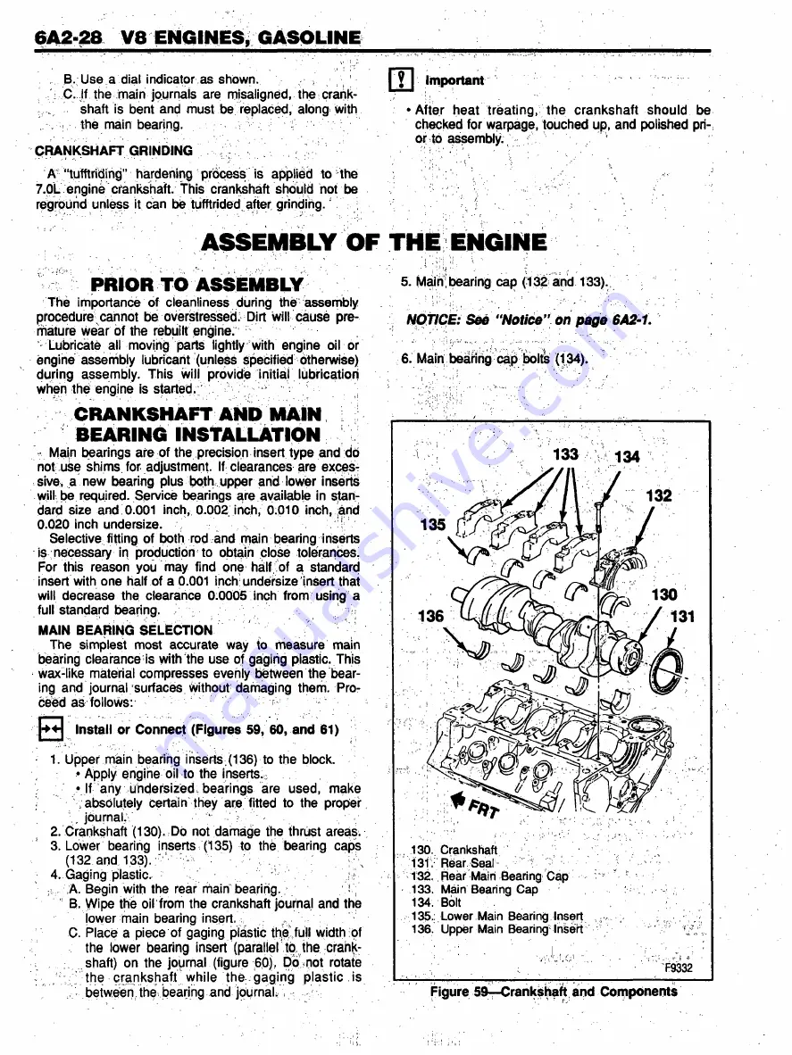
5. Main; bearing cap (132 and 133).
The importance of cleanliness during the assembly
.
!
procedure'cannot be overstressed. Dirt will cause pre-
NOTICE: See “ N o tic e " on page
6 A 2 *1 .
mature wear of the rebuilt engine.
Lubricate all moving parts lightly with engine oil or
;;:-r
;; ^
engine assembly lubricant (unless specified otherwise)
6. Main bearing cap bolts (134).
during assembly. This will provide initial lubrication
when the engine is started.
■
'
CRANKSHAFT AND MAIN
BEARING INSTALLATION
Main bearings are of the precision insert type and do
not use shims for adjustment. If clearances are exces
sive, a new bearing plus both upper and lower inserts
will be required. Service bearings are available in stan
dard size and 0.001 inch, 0.002 inch, 0.010 inch, and
0.020 inch undersize.
|
Selective fitting of both rod and main bearing inserts
is necessary in production to obtain close tolerances.
For this reason you may find one half of a standard
insert with one half of a 0.001 inch undersize insert that
will decrease the clearance 0.0005 inch from using a
full standard bearing.
;
MAIN BEARING SELECTION
The simplest most accurate way to rneasure main
bearing clearance is with the use of gaging plastic. This
wax-like material compresses evenly between the bear
ing and journal surfaces Without damaging them. Pro
ceed as follows:
Install or Connect (Figures 59, 60, and 61)
1. Upper main bearing inserts,(136) to the block.
• Apply engine oil to the inserts.
• If any undersized bearings are used, make
/ absolutely certain they are fitted to the proper.
2. Crankshaft (130). Do not damage the thrust areas.
3. Lower bearing inserts (135) to the bearing caps
5> /A. Begin with the rear main bearing.
B. Wipe the oil from the crankshaft journal and the
lower main bearing insert.
C. Place a piece of gaging plastic the full width of
the lower bearing insert (paraller to, the crank
shaft) on the journal (figure 60), Do not rotate
J > ; the crankshaft while the gaging plastic is
, • between the bearing and journal.
130. Crankshaft
131. Rear Seal ,
v ;
132. Rear Main Bearing Cap
133. Main Bearing Cap
134. Bolt
135. : Lower Main Bearing Insert ,
136. Upper Main Bearing Insert
F9332
Figure 59—Crankshaft and Components
Содержание C Series 1993
Страница 1: ......
Страница 12: ...OA 6 GENERAL INFORMATION Figure 11 Allison Transmission I D Location ...
Страница 44: ...3B1A 2 POWER STEERING GEAR UNIT REPAIR Figure 1 710 Power Steering Gear ...
Страница 62: ......
Страница 75: ...3B3 2 POWER STEERING COMPONENTS TRW ROSS ...
Страница 101: ...5P2 4 HYDRAULIC BOOSTER Figure 5 Removing the Seal Plug Figure 3 Removing the End Cover Assembly ...
Страница 121: ...5H 16 AIR BRAKE VALVES Figure 21 Bendix Proportioning Relay Valve Components ...
Страница 147: ...5J 10 AIR COMPRESSOR AND GOVERNOR 286 F9051 Figure 18 Bendix BX 2150 Compressor Components i ...
Страница 204: ...MODEL 295 TBI UNIT 6C1 3 F7973 Figure 3 Model 295 TBL Unit ...
Страница 251: ...6D4 6 37 MT STARTER MOTORS V3022 Figure 8 37 MT Components ...


