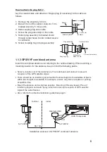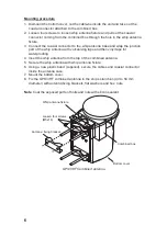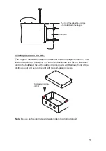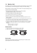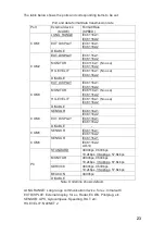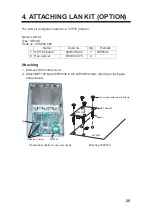
11
1.4 Power Supply (option)
When selecting a mounting location for the unit, keep the following in mind:
•
Keep the unit out away from areas subject to water splash.
•
Locate the unit away from exhaust pipes and vents.
•
The mounting location should be well ventilated.
•
Mount the unit where shock and vibration are minimal.
•
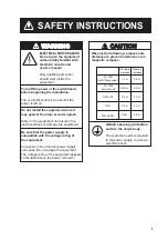
A magnetic compass will be affected if the unit is placed too close to it. Observe
the following compass safe distances to prevent disturbance to the magnetic
compass:
Steering compass: 0.6 m
Standard compass: 0.9 m
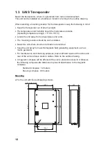
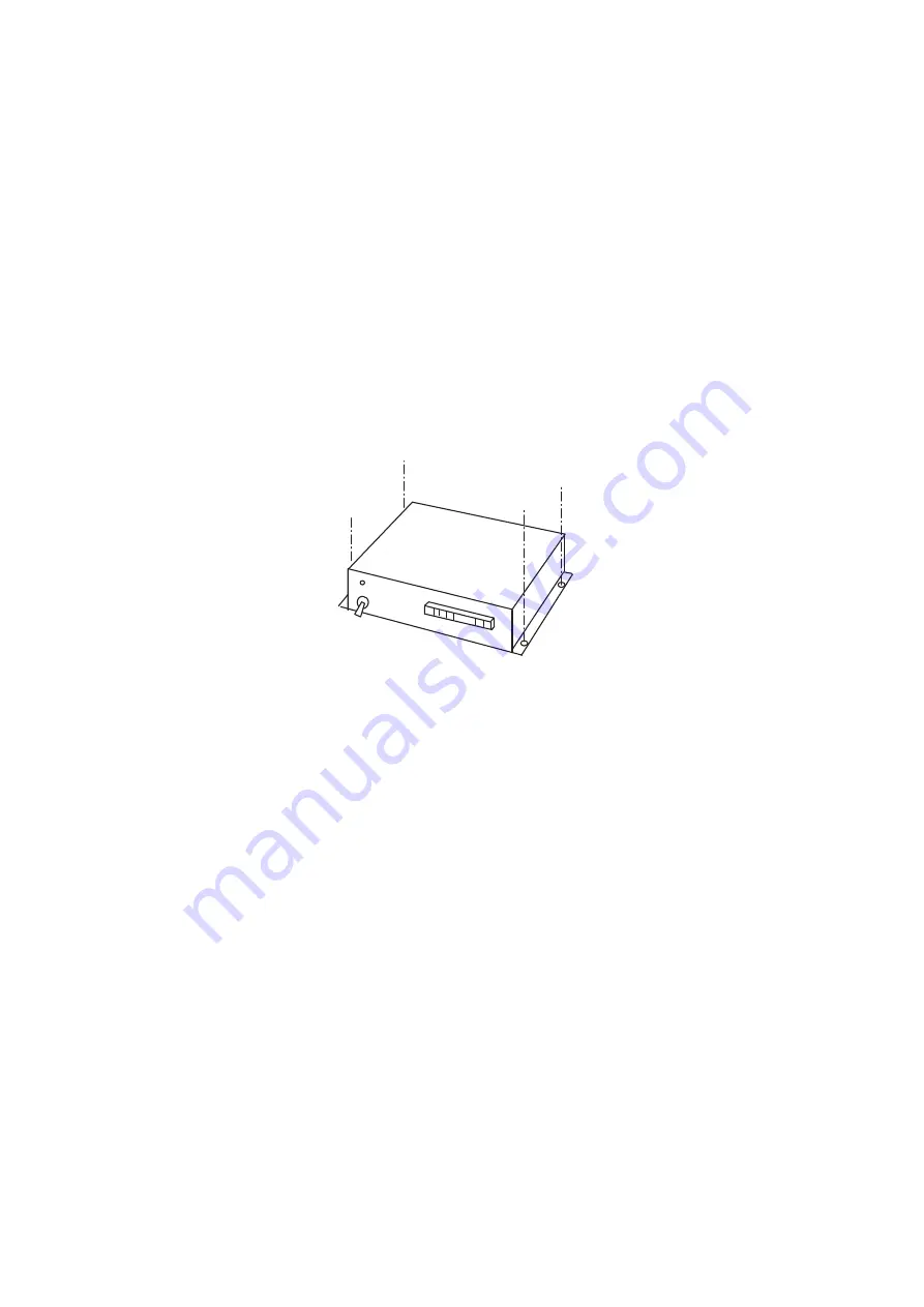
Fix the unit with four self-tapping screws (4x16) to a desktop or the deck as shown
in the figure below. It is not necessary to open the cover.
1.5 Pilot Plug (option)
The pilot plug should be mounted near where the pilot steers the ship. This plug is
used to connect a PC to display AIS information for use by the pilot. Refer to the
outline drawing at the back of this manual for mounting dimensions.
Содержание FA-150
Страница 2: ...This page left intentionally blank ...
Страница 4: ...This page left intentionally blank ...
Страница 5: ...Revision history manual Rev A B C Description Date dd mm yyyy Sign A A 06 05 2015 HAB ...
Страница 6: ...This page left intentionally blank ...
Страница 8: ...This page left intentionally blank ...
Страница 9: ...Index divider Section 1 N ...
Страница 10: ......
Страница 12: ...PRINTED IN JAPAN UAIS TRANSPONDER FA 150 ...
Страница 53: ...Antenna Cable Set CP20 02700 004 381 160 CP20 02710 004 381 170 A 8 ...
Страница 54: ...Antenna cable Set CP24 00300 000 041 938 CP24 00310 000 041 939 A 9 ...
Страница 55: ...Y Hatai D 1 ...
Страница 56: ...Y Hatai D 2 ...
Страница 57: ...Y Hatai D 3 ...
Страница 58: ...Y Hatai D 4 ...
Страница 59: ...Feb 19 03 D 5 ...
Страница 60: ...May 20 03 D 6 ...
Страница 61: ...Feb 22 05 D 7 ...
Страница 62: ...Jan 9 03 D 8 ...
Страница 63: ...Mar 11 04 H Hayashi D 9 ...
Страница 64: ...Feb 02 05 D 10 ...
Страница 65: ...Nov 28 03 D 11 ...
Страница 66: ...Oct 02 03 D 12 ...
Страница 67: ...H Hayashi Mar 10 05 D 13 ...
Страница 69: ...Index divider Section 2 N ...
Страница 70: ......
Страница 72: ...This page left intentionally blank ...
Страница 129: ...Index divider Section 3 N ...
Страница 130: ......
Страница 187: ...Index divider Section 4 N ...
Страница 188: ......
Страница 190: ...TECHNICAL MANUAL A100K11209 v 1 3 Sound Reception System VSS V2 Installation User Manual ...
Страница 204: ...15 VSS V2 Technical Manual A100K11209 v 1 3 4 7 Cable Connection Diagram ...
Страница 205: ...16 A100K11209 v 1 3 VSS V2 Technical Manual 5 Dimensions Mounting Details 5 1 VSS V2 Microphone Unit Dimensions in mm ...
Страница 206: ...17 VSS V2 Technical Manual A100K11209 v 1 3 5 2 VSS V2 Master Panel Dimensions in mm ...
Страница 207: ...18 A100K11209 v 1 3 VSS V2 Technical Manual 5 3 VSS V2 Slave Panel Dimensions in mm ...
Страница 216: ...This page left intentionally blank ...

