20
3.2 Setting GPS Antenna Position
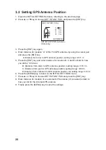
1. Open the INITIAL SETTINGS window, referring to the previous page.
2. Press
Ÿ
or
ź
key to choose SET INT ANT POS. and press the [ENT] key.
[SET INT ANT POS.]
QUIT[MENU]
SET INT ANT POS. sub-menu
(Data entry)
A:
0 m
B:
0 m
C:
0 m
D:
0 m
A
B
C D
3. Press the [ENT] key again.
4. Enter distance for location “A” of FA-150 GPS antenna by using the cursor pad
and press the [ENT] key.
A: Distance from bow to GPS antenna position, setting range: 0-511 m
5. Press the [ENT] key and enter distance for location B, C and D similar to how
you did for "A" above.
B: Distance from stern to GPS antenna position, setting range: 0-511 m
C: Distance from port to GPS antenna position, setting range: 0-63 m
D: Distance from starboard to GPS antenna position, the setting range: 0-63 m
6. Press the [MENU] key to return to the INITIAL SETTINGS menu.
7. Press
Ÿ
or
ź
key to choose SET EXT ANT POS and press the [ENT] key.
8. Enter distance for location of an external GPS antenna (if connected) similar to
how you did for the internal GPS antenna.
9. Finally press the [MENU] key to save the settings.
Содержание FA-150
Страница 2: ...This page left intentionally blank ...
Страница 4: ...This page left intentionally blank ...
Страница 5: ...Revision history manual Rev A B C Description Date dd mm yyyy Sign A A 06 05 2015 HAB ...
Страница 6: ...This page left intentionally blank ...
Страница 8: ...This page left intentionally blank ...
Страница 9: ...Index divider Section 1 N ...
Страница 10: ......
Страница 12: ...PRINTED IN JAPAN UAIS TRANSPONDER FA 150 ...
Страница 53: ...Antenna Cable Set CP20 02700 004 381 160 CP20 02710 004 381 170 A 8 ...
Страница 54: ...Antenna cable Set CP24 00300 000 041 938 CP24 00310 000 041 939 A 9 ...
Страница 55: ...Y Hatai D 1 ...
Страница 56: ...Y Hatai D 2 ...
Страница 57: ...Y Hatai D 3 ...
Страница 58: ...Y Hatai D 4 ...
Страница 59: ...Feb 19 03 D 5 ...
Страница 60: ...May 20 03 D 6 ...
Страница 61: ...Feb 22 05 D 7 ...
Страница 62: ...Jan 9 03 D 8 ...
Страница 63: ...Mar 11 04 H Hayashi D 9 ...
Страница 64: ...Feb 02 05 D 10 ...
Страница 65: ...Nov 28 03 D 11 ...
Страница 66: ...Oct 02 03 D 12 ...
Страница 67: ...H Hayashi Mar 10 05 D 13 ...
Страница 69: ...Index divider Section 2 N ...
Страница 70: ......
Страница 72: ...This page left intentionally blank ...
Страница 129: ...Index divider Section 3 N ...
Страница 130: ......
Страница 187: ...Index divider Section 4 N ...
Страница 188: ......
Страница 190: ...TECHNICAL MANUAL A100K11209 v 1 3 Sound Reception System VSS V2 Installation User Manual ...
Страница 204: ...15 VSS V2 Technical Manual A100K11209 v 1 3 4 7 Cable Connection Diagram ...
Страница 205: ...16 A100K11209 v 1 3 VSS V2 Technical Manual 5 Dimensions Mounting Details 5 1 VSS V2 Microphone Unit Dimensions in mm ...
Страница 206: ...17 VSS V2 Technical Manual A100K11209 v 1 3 5 2 VSS V2 Master Panel Dimensions in mm ...
Страница 207: ...18 A100K11209 v 1 3 VSS V2 Technical Manual 5 3 VSS V2 Slave Panel Dimensions in mm ...
Страница 216: ...This page left intentionally blank ...

