


U
lstein Power & Control AS
This document and its content is the property of ULSTEIN. Non-
public information contained herein shall be treated as
Confidential Information. No use, copying, citation or publication
of this document or its content is permitted without prior written
consent from ULSTEIN. Any conflicts arising from unauthorized
use shall be governed by the laws of Norway.
File Name:
BRI-D32004-01II (D)
System Installation
Manual.doc
Page:
Page 11 of
56
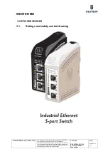
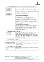
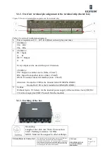
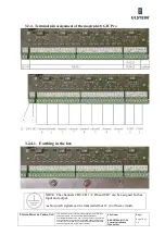
2.2.4.3.
DIGITAL OUTPUT / INPUT: (X1 DIG OUT / X1 DIG IN
A mechanical and digitally driven “Solid State Relay”
(NO/NC/COM/24VDC) (over current protection) which
allows the user via software to control external equipment that
require or are compatible with the specifications. Connect and
fasten your cables from your compatible external equipment
to the SCD 90F connector block.
Brief explanation for X1 DIG In:
DIO0_GPI4 signal is normally high. Can be read via software.
If it is applied to 24V (12V also works) of between 24
VDC and GND, the DIO0_GPI4 signal will goes to low
status. DIO0_GPI5 signal is normally low. Can be read via
software. If it is applied to 24V (12V works well) between the
input+ and +24 VDC, the DIO0_GPI5 signal will go high
To short-circuit input+ and +24VDC works too, as there is
12V on +24VDC.
Brief explanation for X1 DIG OUT:
HS1_OUT and DIO0_GP05 signals, which are managed via
software, checks if the HS1 relay is on, and thus the pin 1
(HS1+) and pin 2 (OUT1-) is connected. DIO1_GPOU6
signal controls whether HS2 is on, and thus pin 3 (K3+) and
pin 4 (K3-) is connected.
2.2.4.4.
USB INPUT / OUTPUT
Supports any USB1.1 (12Mbps) and USB2.0 (480Mbps) compliant
peripherals. Drivers for most USB devices are usually included in
operating system or on separate installation DVD’s delivered with Third
Party products. USB 1.1 devices will operate in USB 1.1 mode (12 Mbps).
USB1.1 is suitable for cable distances above 10meter/32.8 feet, whereas
USB2.0 is suitable from less than 10meter/32.8 feet distances. Based on
model, 2 or 4 ports is available.
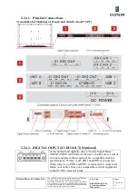
2.2.4.5.
POWER INPUTS
Connect your DC power cables to the SL-SMT 90F connector block. The
internal DC power module supports 24VDC.
The unit offer both Primary and Secondary power inputs for secure
operation of the unit as well as; galvanic isolated and automatic switch
between power sources.
2.2.4.6.
GROUNDING SCREW
DC models are required / recommended to be properly grounded via the
grounding
screw located on the unit.
Содержание FA-150
Страница 2: ...This page left intentionally blank ...
Страница 4: ...This page left intentionally blank ...
Страница 5: ...Revision history manual Rev A B C Description Date dd mm yyyy Sign A A 06 05 2015 HAB ...
Страница 6: ...This page left intentionally blank ...
Страница 8: ...This page left intentionally blank ...
Страница 9: ...Index divider Section 1 N ...
Страница 10: ......
Страница 12: ...PRINTED IN JAPAN UAIS TRANSPONDER FA 150 ...
Страница 53: ...Antenna Cable Set CP20 02700 004 381 160 CP20 02710 004 381 170 A 8 ...
Страница 54: ...Antenna cable Set CP24 00300 000 041 938 CP24 00310 000 041 939 A 9 ...
Страница 55: ...Y Hatai D 1 ...
Страница 56: ...Y Hatai D 2 ...
Страница 57: ...Y Hatai D 3 ...
Страница 58: ...Y Hatai D 4 ...
Страница 59: ...Feb 19 03 D 5 ...
Страница 60: ...May 20 03 D 6 ...
Страница 61: ...Feb 22 05 D 7 ...
Страница 62: ...Jan 9 03 D 8 ...
Страница 63: ...Mar 11 04 H Hayashi D 9 ...
Страница 64: ...Feb 02 05 D 10 ...
Страница 65: ...Nov 28 03 D 11 ...
Страница 66: ...Oct 02 03 D 12 ...
Страница 67: ...H Hayashi Mar 10 05 D 13 ...
Страница 69: ...Index divider Section 2 N ...
Страница 70: ......
Страница 72: ...This page left intentionally blank ...
Страница 129: ...Index divider Section 3 N ...
Страница 130: ......
Страница 187: ...Index divider Section 4 N ...
Страница 188: ......
Страница 190: ...TECHNICAL MANUAL A100K11209 v 1 3 Sound Reception System VSS V2 Installation User Manual ...
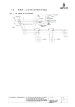
Страница 204: ...15 VSS V2 Technical Manual A100K11209 v 1 3 4 7 Cable Connection Diagram ...
Страница 205: ...16 A100K11209 v 1 3 VSS V2 Technical Manual 5 Dimensions Mounting Details 5 1 VSS V2 Microphone Unit Dimensions in mm ...
Страница 206: ...17 VSS V2 Technical Manual A100K11209 v 1 3 5 2 VSS V2 Master Panel Dimensions in mm ...
Страница 207: ...18 A100K11209 v 1 3 VSS V2 Technical Manual 5 3 VSS V2 Slave Panel Dimensions in mm ...
Страница 216: ...This page left intentionally blank ...


