10
1.3 UAIS
Transponder
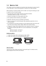
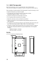
Mount the transponder, where it is protected from rain and water splash.
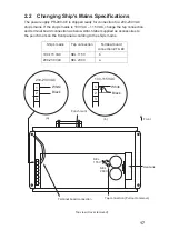
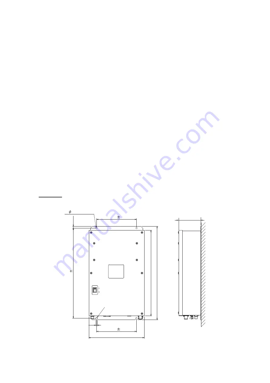
This unit can be installed on a bulkhead. Install it, referring to the outline drawing.
When selecting a mounting location for the transponder, keep the following in mind:
•
Keep the transponder out of direct sunlight.
•
The temperature and humidity should be moderate and stable.
(Operating temperature range: -15°C to +55°C)
•
Locate the unit away from exhaust pipes and vents.
•
The mounting location should be well ventilated.
•
Mount the unit where shock and vibration are minimal.
•
Keep the unit away from electromagnetic field generating equipment such as
motor, generator.
•
For maintenance and checking purposes, leave sufficient space at the sides and
rear of the unit and leave slack in cables. Refer to the outline drawing.
•
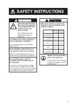
A magnetic compass will be affected if the unit is placed too close to it. Observe
the following compass safe distances to prevent disturbance to the magnetic
compass:
Standard compass:
1.2
meters
Steering compass:
0.8
meters
Mounting
Ɣ
Fix the unit with four self-tapping screws.
POWER
385
420
7
180 1
250
R3.5
405
1
7.5
180 1
2- 7
Fixing
holes
100
Содержание FA-150
Страница 2: ...This page left intentionally blank ...
Страница 4: ...This page left intentionally blank ...
Страница 5: ...Revision history manual Rev A B C Description Date dd mm yyyy Sign A A 06 05 2015 HAB ...
Страница 6: ...This page left intentionally blank ...
Страница 8: ...This page left intentionally blank ...
Страница 9: ...Index divider Section 1 N ...
Страница 10: ......
Страница 12: ...PRINTED IN JAPAN UAIS TRANSPONDER FA 150 ...
Страница 53: ...Antenna Cable Set CP20 02700 004 381 160 CP20 02710 004 381 170 A 8 ...
Страница 54: ...Antenna cable Set CP24 00300 000 041 938 CP24 00310 000 041 939 A 9 ...
Страница 55: ...Y Hatai D 1 ...
Страница 56: ...Y Hatai D 2 ...
Страница 57: ...Y Hatai D 3 ...
Страница 58: ...Y Hatai D 4 ...
Страница 59: ...Feb 19 03 D 5 ...
Страница 60: ...May 20 03 D 6 ...
Страница 61: ...Feb 22 05 D 7 ...
Страница 62: ...Jan 9 03 D 8 ...
Страница 63: ...Mar 11 04 H Hayashi D 9 ...
Страница 64: ...Feb 02 05 D 10 ...
Страница 65: ...Nov 28 03 D 11 ...
Страница 66: ...Oct 02 03 D 12 ...
Страница 67: ...H Hayashi Mar 10 05 D 13 ...
Страница 69: ...Index divider Section 2 N ...
Страница 70: ......
Страница 72: ...This page left intentionally blank ...
Страница 129: ...Index divider Section 3 N ...
Страница 130: ......
Страница 187: ...Index divider Section 4 N ...
Страница 188: ......
Страница 190: ...TECHNICAL MANUAL A100K11209 v 1 3 Sound Reception System VSS V2 Installation User Manual ...
Страница 204: ...15 VSS V2 Technical Manual A100K11209 v 1 3 4 7 Cable Connection Diagram ...
Страница 205: ...16 A100K11209 v 1 3 VSS V2 Technical Manual 5 Dimensions Mounting Details 5 1 VSS V2 Microphone Unit Dimensions in mm ...
Страница 206: ...17 VSS V2 Technical Manual A100K11209 v 1 3 5 2 VSS V2 Master Panel Dimensions in mm ...
Страница 207: ...18 A100K11209 v 1 3 VSS V2 Technical Manual 5 3 VSS V2 Slave Panel Dimensions in mm ...
Страница 216: ...This page left intentionally blank ...

