


20
A100K11209 v.1.3
VSS-V2 Technical Manual
7 Operating Instructions
7.1 Panel Operation
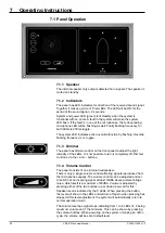
7.1.1 Speaker
The internal speaker only outputs detected horn signals. The speaker is
muted on standby.
7.1.2 Indicators
The panel has LED indicators for direction of the received sound signal.
Together it makes a circle of 8 red LEDs. The LED will be ON for the
period of the sound 2 seconds.
System and power LED (green) is lit steadily when the system is
functional with no errors. A fault in the system will make the system
LED flash. If the fault is in one of the microphones, the corresponding
microphone LED will be flashing as well. Faulty flashing frequency for
both LEDs is 200ms toggle.
The system LED indicates active override function by flashing. Override
flashing frequency is 1s toggle.
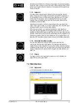
7.1.3 Dimmer
The panel has dimmer control on the front panel to adjust the light
intensity of the LEDs. It is not possible to turn it completely off. Dimmer
control is via the + and – buttons.
7.1.4 Volume Control
The panel consists of one internal loudspeaker.
There is only a single volume control affecting signals reproduced from
the microphones equally. The volume control can be adjusted and set
to an SPL of an incoming signal at least 10dBA above ambient bridge
noise, which itself is a maximum of 65dBA. Volume is adjusted by
pressing either of the two buttons (up or down) reserved for this.
Speaker level is indicated by the 8 LEDs. When pressing the button,
the level will show in the LEDs and will turn off again when pressing has
stopped. After level adjustment, the system will automatically return to
normal operation mode.
The volume level has eight steps indicating from 1 to 8 LEDs lit, 8 being
maximum volume and 1 the minimum. This can be shown by pressing
the volume buttons. When powering on the system or making an off/on
cycle, the volume will be set at default level.
Содержание FA-150
Страница 2: ...This page left intentionally blank ...
Страница 4: ...This page left intentionally blank ...
Страница 5: ...Revision history manual Rev A B C Description Date dd mm yyyy Sign A A 06 05 2015 HAB ...
Страница 6: ...This page left intentionally blank ...
Страница 8: ...This page left intentionally blank ...
Страница 9: ...Index divider Section 1 N ...
Страница 10: ......
Страница 12: ...PRINTED IN JAPAN UAIS TRANSPONDER FA 150 ...
Страница 53: ...Antenna Cable Set CP20 02700 004 381 160 CP20 02710 004 381 170 A 8 ...
Страница 54: ...Antenna cable Set CP24 00300 000 041 938 CP24 00310 000 041 939 A 9 ...
Страница 55: ...Y Hatai D 1 ...
Страница 56: ...Y Hatai D 2 ...
Страница 57: ...Y Hatai D 3 ...
Страница 58: ...Y Hatai D 4 ...
Страница 59: ...Feb 19 03 D 5 ...
Страница 60: ...May 20 03 D 6 ...
Страница 61: ...Feb 22 05 D 7 ...
Страница 62: ...Jan 9 03 D 8 ...
Страница 63: ...Mar 11 04 H Hayashi D 9 ...
Страница 64: ...Feb 02 05 D 10 ...
Страница 65: ...Nov 28 03 D 11 ...
Страница 66: ...Oct 02 03 D 12 ...
Страница 67: ...H Hayashi Mar 10 05 D 13 ...
Страница 69: ...Index divider Section 2 N ...
Страница 70: ......
Страница 72: ...This page left intentionally blank ...
Страница 129: ...Index divider Section 3 N ...
Страница 130: ......
Страница 187: ...Index divider Section 4 N ...
Страница 188: ......
Страница 190: ...TECHNICAL MANUAL A100K11209 v 1 3 Sound Reception System VSS V2 Installation User Manual ...
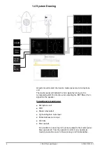
Страница 204: ...15 VSS V2 Technical Manual A100K11209 v 1 3 4 7 Cable Connection Diagram ...
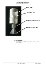
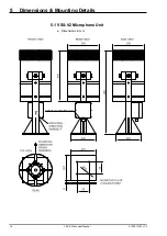
Страница 205: ...16 A100K11209 v 1 3 VSS V2 Technical Manual 5 Dimensions Mounting Details 5 1 VSS V2 Microphone Unit Dimensions in mm ...
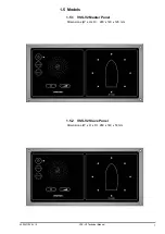
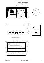
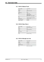
Страница 206: ...17 VSS V2 Technical Manual A100K11209 v 1 3 5 2 VSS V2 Master Panel Dimensions in mm ...
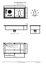
Страница 207: ...18 A100K11209 v 1 3 VSS V2 Technical Manual 5 3 VSS V2 Slave Panel Dimensions in mm ...
Страница 216: ...This page left intentionally blank ...


