11
VSS-V2 Technical Manual
A100K11209 v.1.3
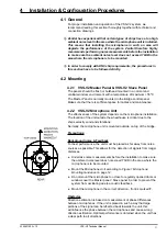
4 Installation & Configuration Procedures
4.1 General
For proper installation and operation of the VSS-V2 system, we
recommend reading this section thoroughly together with technical and
connection drawings.
L
Zenitel has experienced that certain types of ships have a too high
ambient noise level in the area where the microphone unit is installed.
This means that installing the microphone in such an area will
degrade the performance of the system. Zenitel therefore highly
recommends performing noise measurements before the installation
to make sure the ambient noise level does not exceed 70dB in the
area where the microphone is to be mounted.
L
In order to comply with DNV ship requirements, the procedures in
this section have to be followed strictly.
4.2 Mounting
4.2.1 VSS-V2 Master Panel & VSS-V2 Slave Panel
The panels should be flush or bulkhead mounted in a normal and
ventilated indoor environment with a temperature of m55 ºC.
The Master Panel is normally mounted in the Bridge control panel.
Make sure that there is sufficient space for cables and maintenance.
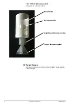
4.2.2 VSS-V2 Microphone Unit
The effectiveness of the system depends on the microphone installation.
The location of the unit outside the wheelhouse is critical due to the
ship’s velocity, wind and vibrations.
Normally, the microphone unit is mounted outside, on top of the bridge.
Precautions:
Background noise & Feedback
For best performance, the unit must be placed as far away from noise
sources as possible. This allows for the detection of signals from longer
distances.
●
Undertake noise measurements before the installation to make sure
the ambient noise level does not exceed 70dB in the area where the
microphone is to be mounted.
●
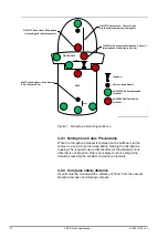
Mount the Microphone Unit according to
Figure 1 Microphone
Mounting Guidance
on page 12.
●
Do not mount the microphone too close to regularly opened doors or
windows near the Master panel / Slave panel in order to prevent the
system from oscillating due to acoustic feedback.
●
Mount the microphone in the correct direction - front is marked
F
.
Obstacles
Direction estimation is based on measurement of phase differences
between microphones. If the unit is placed in such a way that large
portions of the signal can be reflected back towards the unit, this
will influence the phase between the microphones and cause wrong
direction estimation. Optimal performance is obtained when the unit has
a clear path to all directions.
Содержание FA-150
Страница 2: ...This page left intentionally blank ...
Страница 4: ...This page left intentionally blank ...
Страница 5: ...Revision history manual Rev A B C Description Date dd mm yyyy Sign A A 06 05 2015 HAB ...
Страница 6: ...This page left intentionally blank ...
Страница 8: ...This page left intentionally blank ...
Страница 9: ...Index divider Section 1 N ...
Страница 10: ......
Страница 12: ...PRINTED IN JAPAN UAIS TRANSPONDER FA 150 ...
Страница 53: ...Antenna Cable Set CP20 02700 004 381 160 CP20 02710 004 381 170 A 8 ...
Страница 54: ...Antenna cable Set CP24 00300 000 041 938 CP24 00310 000 041 939 A 9 ...
Страница 55: ...Y Hatai D 1 ...
Страница 56: ...Y Hatai D 2 ...
Страница 57: ...Y Hatai D 3 ...
Страница 58: ...Y Hatai D 4 ...
Страница 59: ...Feb 19 03 D 5 ...
Страница 60: ...May 20 03 D 6 ...
Страница 61: ...Feb 22 05 D 7 ...
Страница 62: ...Jan 9 03 D 8 ...
Страница 63: ...Mar 11 04 H Hayashi D 9 ...
Страница 64: ...Feb 02 05 D 10 ...
Страница 65: ...Nov 28 03 D 11 ...
Страница 66: ...Oct 02 03 D 12 ...
Страница 67: ...H Hayashi Mar 10 05 D 13 ...
Страница 69: ...Index divider Section 2 N ...
Страница 70: ......
Страница 72: ...This page left intentionally blank ...
Страница 129: ...Index divider Section 3 N ...
Страница 130: ......
Страница 187: ...Index divider Section 4 N ...
Страница 188: ......
Страница 190: ...TECHNICAL MANUAL A100K11209 v 1 3 Sound Reception System VSS V2 Installation User Manual ...
Страница 204: ...15 VSS V2 Technical Manual A100K11209 v 1 3 4 7 Cable Connection Diagram ...
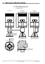
Страница 205: ...16 A100K11209 v 1 3 VSS V2 Technical Manual 5 Dimensions Mounting Details 5 1 VSS V2 Microphone Unit Dimensions in mm ...
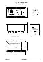
Страница 206: ...17 VSS V2 Technical Manual A100K11209 v 1 3 5 2 VSS V2 Master Panel Dimensions in mm ...
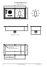
Страница 207: ...18 A100K11209 v 1 3 VSS V2 Technical Manual 5 3 VSS V2 Slave Panel Dimensions in mm ...
Страница 216: ...This page left intentionally blank ...

