19
VSS-V2 Technical Manual
A100K11209 v.1.3
6 Startup and Commissioning of System
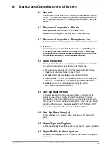
6.1 General
The VSS-V2 units have been fully tested in our test laboratory before
delivery. To ensure that the system operates properly after installation
and configuration, carry out the following procedures before using the
system.
6.2 Mechanical Inspection - Panels
● All equipment is well fastened in the console or wall.
● All cable and cable glands are well tightened and fastened.
6.3 Mechanical Inspection - Microphone Unit
The unit is installed according to procedures described in section 4.2.2.
L
Important!
The microphones shall be installed in such a way that they are
as far away from noise sources on the vessel as is practically
possible, where wind-induced noise from objects (such as wires )
and mechanical vibrations are reasonably reduced.
6.4 Cable Inspection
Make sure that all cables are connected according to section
4.7 Cable
Connection Diagram
and check all terminals. Check that:
●
All signal cables are min. 0.75 mm
2
approved ship cable of type
twisted-pair with outer braided copper shield
●
All cable shields are connected to the ground terminals
●
Power cable is 0.75 mm
2
and connected to terminal block K9 (+ to
terminal 1, - to terminal 2). The shield is grounded on terminal 3.
●
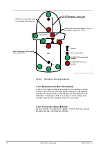
Cable for microphone is arranged according to section
4.2.3 Microphone Cable Precautions
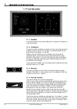
6.5 Start Up Master Panel
Set master panels to on. When the green status / self test LED is
steadily lit, use a horn or similar device that sends out harmonic
signals with a higher SPL than the background noise to activate each
microphone. The master panel shall activate the diode from the correct
direction. At the minimum, check all sides FWD, AFT, STB and PORT.
See section
7 Operating Procedures
for all other functions.
6.6 Start Up Slave Panel(s)
Set slave panels to on. Use the same procedure as for the master
panel.
6.7 Ship’s Typhoon/Foghorn
Activate the ship’s typhoon/foghorn and check that the system is muted.
6.8 Ship’s Public Address System
Broadcast a PA message and check whether the VSS-V2 microphones
are muted.
Содержание FA-150
Страница 2: ...This page left intentionally blank ...
Страница 4: ...This page left intentionally blank ...
Страница 5: ...Revision history manual Rev A B C Description Date dd mm yyyy Sign A A 06 05 2015 HAB ...
Страница 6: ...This page left intentionally blank ...
Страница 8: ...This page left intentionally blank ...
Страница 9: ...Index divider Section 1 N ...
Страница 10: ......
Страница 12: ...PRINTED IN JAPAN UAIS TRANSPONDER FA 150 ...
Страница 53: ...Antenna Cable Set CP20 02700 004 381 160 CP20 02710 004 381 170 A 8 ...
Страница 54: ...Antenna cable Set CP24 00300 000 041 938 CP24 00310 000 041 939 A 9 ...
Страница 55: ...Y Hatai D 1 ...
Страница 56: ...Y Hatai D 2 ...
Страница 57: ...Y Hatai D 3 ...
Страница 58: ...Y Hatai D 4 ...
Страница 59: ...Feb 19 03 D 5 ...
Страница 60: ...May 20 03 D 6 ...
Страница 61: ...Feb 22 05 D 7 ...
Страница 62: ...Jan 9 03 D 8 ...
Страница 63: ...Mar 11 04 H Hayashi D 9 ...
Страница 64: ...Feb 02 05 D 10 ...
Страница 65: ...Nov 28 03 D 11 ...
Страница 66: ...Oct 02 03 D 12 ...
Страница 67: ...H Hayashi Mar 10 05 D 13 ...
Страница 69: ...Index divider Section 2 N ...
Страница 70: ......
Страница 72: ...This page left intentionally blank ...
Страница 129: ...Index divider Section 3 N ...
Страница 130: ......
Страница 187: ...Index divider Section 4 N ...
Страница 188: ......
Страница 190: ...TECHNICAL MANUAL A100K11209 v 1 3 Sound Reception System VSS V2 Installation User Manual ...
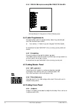
Страница 204: ...15 VSS V2 Technical Manual A100K11209 v 1 3 4 7 Cable Connection Diagram ...
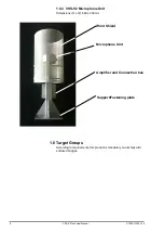
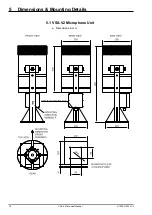
Страница 205: ...16 A100K11209 v 1 3 VSS V2 Technical Manual 5 Dimensions Mounting Details 5 1 VSS V2 Microphone Unit Dimensions in mm ...
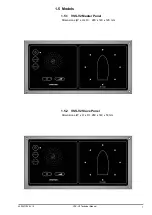
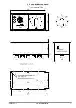
Страница 206: ...17 VSS V2 Technical Manual A100K11209 v 1 3 5 2 VSS V2 Master Panel Dimensions in mm ...
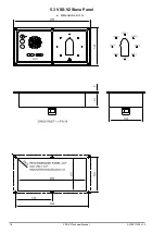
Страница 207: ...18 A100K11209 v 1 3 VSS V2 Technical Manual 5 3 VSS V2 Slave Panel Dimensions in mm ...
Страница 216: ...This page left intentionally blank ...

