6
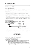
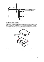
Mounting procedure
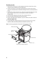
1. Dismount the bottom cover, cut the cable-tie inside the unit and take out the
coaxial connector attached to the combined box.
2. Loosen four screws to loosen whip antenna fixture and pull out the coaxial
connector coming from the combined box through the hole in the whip antenna
fixture.
3. Connect the coaxial connector to the whip antenna base and wrap the junction
part of the whip antenna with vulcanizing tape and then vinyl tape for
waterproofing.
4. Insert the whip antenna from the top of the combined antenna.
5. Secure the whip antenna with whip antenna fixture.
6. Using a new plastic band (supplied), secure the cables and coaxial connector
inside the antenna case.
7. Mount the bottom cover.
8. Fix the GPS/VHF combined antenna to the ship’s stanchion (40 to 50 mm
diameter) with antenna fixing brackets, flat washers and hex. nuts.
Note
: Coat the exposed parts of bolts and nuts with silicon sealant.
Antenna fixing bracket
Loosen four screws.
(M5x16)
Bottom cover
Combined box
Whip antenna fixture
GPS/VHF Combined antenna
Содержание FA-150
Страница 2: ...This page left intentionally blank ...
Страница 4: ...This page left intentionally blank ...
Страница 5: ...Revision history manual Rev A B C Description Date dd mm yyyy Sign A A 06 05 2015 HAB ...
Страница 6: ...This page left intentionally blank ...
Страница 8: ...This page left intentionally blank ...
Страница 9: ...Index divider Section 1 N ...
Страница 10: ......
Страница 12: ...PRINTED IN JAPAN UAIS TRANSPONDER FA 150 ...
Страница 53: ...Antenna Cable Set CP20 02700 004 381 160 CP20 02710 004 381 170 A 8 ...
Страница 54: ...Antenna cable Set CP24 00300 000 041 938 CP24 00310 000 041 939 A 9 ...
Страница 55: ...Y Hatai D 1 ...
Страница 56: ...Y Hatai D 2 ...
Страница 57: ...Y Hatai D 3 ...
Страница 58: ...Y Hatai D 4 ...
Страница 59: ...Feb 19 03 D 5 ...
Страница 60: ...May 20 03 D 6 ...
Страница 61: ...Feb 22 05 D 7 ...
Страница 62: ...Jan 9 03 D 8 ...
Страница 63: ...Mar 11 04 H Hayashi D 9 ...
Страница 64: ...Feb 02 05 D 10 ...
Страница 65: ...Nov 28 03 D 11 ...
Страница 66: ...Oct 02 03 D 12 ...
Страница 67: ...H Hayashi Mar 10 05 D 13 ...
Страница 69: ...Index divider Section 2 N ...
Страница 70: ......
Страница 72: ...This page left intentionally blank ...
Страница 129: ...Index divider Section 3 N ...
Страница 130: ......
Страница 187: ...Index divider Section 4 N ...
Страница 188: ......
Страница 190: ...TECHNICAL MANUAL A100K11209 v 1 3 Sound Reception System VSS V2 Installation User Manual ...
Страница 204: ...15 VSS V2 Technical Manual A100K11209 v 1 3 4 7 Cable Connection Diagram ...
Страница 205: ...16 A100K11209 v 1 3 VSS V2 Technical Manual 5 Dimensions Mounting Details 5 1 VSS V2 Microphone Unit Dimensions in mm ...
Страница 206: ...17 VSS V2 Technical Manual A100K11209 v 1 3 5 2 VSS V2 Master Panel Dimensions in mm ...
Страница 207: ...18 A100K11209 v 1 3 VSS V2 Technical Manual 5 3 VSS V2 Slave Panel Dimensions in mm ...
Страница 216: ...This page left intentionally blank ...


