U
lstein Power & Control AS
This document and its content is the property of ULSTEIN. Non-
public information contained herein shall be treated as
Confidential Information. No use, copying, citation or publication
of this document or its content is permitted without prior written
consent from ULSTEIN. Any conflicts arising from unauthorized
use shall be governed by the laws of Norway.
File Name:
BRI-D32004-01II (D)
System Installation
Manual.doc
Page:
Page 23 of
56
unlimited
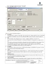
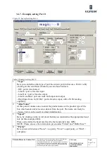
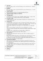
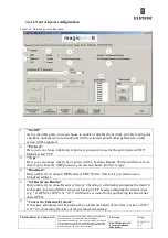
NOTE: Scrollbars appear automatically when the list is to small
7
Interval:
By using the arrow keys or by overwriting the value in the field, you can set the interval (in
seconds) for the logging. Valid values are between 15 and 5000seconds.
8
Debug port:
This field is used to enter the IP port on which debug information from the box can be read.
9
Set Time and Date(UTC):
These fields can be used to set a new date and time on the box. The two field are used to define
the value of the date and time to use, then clicking the button ”Set Time Date(UTC)” will
configure the box to use these ad the current date and time. The given value must be UTC
values.
10
Read firmware version:
By clicking this button, the current version of the box firmware will be displayed in the field 17
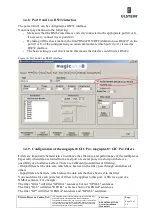
11
Save configuration:
By using the “save configuration” button you case the actual settings of the magicplex8 on the
computer.
12
Download config:
By using the “download config” button you download the actual configuration from the box and
take if over into the configuration software. This will restart the configuration software.
13
Upload configuration:
By clicking on upload configuration the new configuration will be transferred to the box. The
box will then restart by self.
14
Firmware update:
This button allows you to update the firmware on the firmware on the multiplexer. You have
then to select the insf file which contains the instructions to update the firmware. The required
files will then be updated to the multiplexer, which will automatically restart after the update.
15
Exit:
By using the Exit button the configuration software magicplex8 GIC Pro is closed.
16
Configuration Name / Configuration Date.
Information fields displaying the name of the current configuration, and the date and time when
it was created
17
Frimware Version
In this field the current version of the box firmware is displayed after the user clicks on the
button “Read firmware version” (10)
18
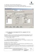
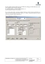
Network configuration
Содержание FA-150
Страница 2: ...This page left intentionally blank ...
Страница 4: ...This page left intentionally blank ...
Страница 5: ...Revision history manual Rev A B C Description Date dd mm yyyy Sign A A 06 05 2015 HAB ...
Страница 6: ...This page left intentionally blank ...
Страница 8: ...This page left intentionally blank ...
Страница 9: ...Index divider Section 1 N ...
Страница 10: ......
Страница 12: ...PRINTED IN JAPAN UAIS TRANSPONDER FA 150 ...
Страница 53: ...Antenna Cable Set CP20 02700 004 381 160 CP20 02710 004 381 170 A 8 ...
Страница 54: ...Antenna cable Set CP24 00300 000 041 938 CP24 00310 000 041 939 A 9 ...
Страница 55: ...Y Hatai D 1 ...
Страница 56: ...Y Hatai D 2 ...
Страница 57: ...Y Hatai D 3 ...
Страница 58: ...Y Hatai D 4 ...
Страница 59: ...Feb 19 03 D 5 ...
Страница 60: ...May 20 03 D 6 ...
Страница 61: ...Feb 22 05 D 7 ...
Страница 62: ...Jan 9 03 D 8 ...
Страница 63: ...Mar 11 04 H Hayashi D 9 ...
Страница 64: ...Feb 02 05 D 10 ...
Страница 65: ...Nov 28 03 D 11 ...
Страница 66: ...Oct 02 03 D 12 ...
Страница 67: ...H Hayashi Mar 10 05 D 13 ...
Страница 69: ...Index divider Section 2 N ...
Страница 70: ......
Страница 72: ...This page left intentionally blank ...
Страница 129: ...Index divider Section 3 N ...
Страница 130: ......
Страница 187: ...Index divider Section 4 N ...
Страница 188: ......
Страница 190: ...TECHNICAL MANUAL A100K11209 v 1 3 Sound Reception System VSS V2 Installation User Manual ...
Страница 204: ...15 VSS V2 Technical Manual A100K11209 v 1 3 4 7 Cable Connection Diagram ...
Страница 205: ...16 A100K11209 v 1 3 VSS V2 Technical Manual 5 Dimensions Mounting Details 5 1 VSS V2 Microphone Unit Dimensions in mm ...
Страница 206: ...17 VSS V2 Technical Manual A100K11209 v 1 3 5 2 VSS V2 Master Panel Dimensions in mm ...
Страница 207: ...18 A100K11209 v 1 3 VSS V2 Technical Manual 5 3 VSS V2 Slave Panel Dimensions in mm ...
Страница 216: ...This page left intentionally blank ...

