4.
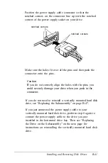
Position
power
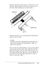
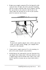
supply connector P4 so the large tab on the
connector faces the right side of the computer. Beginning
with the six pins toward the back of the computer, carefully
line up the holes in the connector with the pins in the
socket. Make sure the holes fit over all six pins and then
push the connector onto the pins.
Caution
If you do not correctly align
the holes with the
pins in the
socket, you could severely damage your computer when
you push in the connector.
5.
Connect power supply connector P5 to the remaining six
pins in the socket using the same procedure.
6.
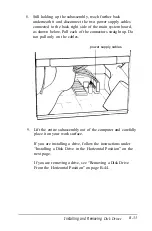
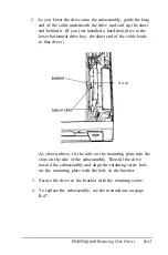
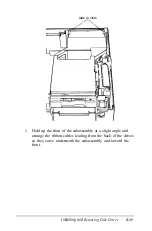
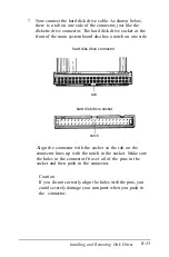
Still holding up the subassembly, locate the hard disk drive
and diskette drive ribbon cables. (The hard disk drive cable
is slightly longer than the diskette drive cable.) Look at the
back of each drive to make sure you know which cable is
which.
Installing and
Removing Disk Drives
B-51
Содержание Equity 386/25
Страница 1: ......
Страница 3: ......
Страница 14: ...xii ...
Страница 20: ...6 lntroduction ...
Страница 63: ...Hard disk drive types continued Running the Setup Program 2 25 ...
Страница 142: ...5 34 lnstalling and Removing Options ...
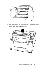
Страница 216: ...3 Raise the front of the subassembly to a slight angle as shown below Installing and Removing Disk Drives B 19 ...
Страница 248: ...C 14 Physically Formatting a Hard Disk ...
Страница 298: ...F 6 Specifications ...
Страница 326: ......

