


User Manual
Chapter 3
GFK-1742F
Jan 2020
Installing and Wiring the DSM314
69
3.
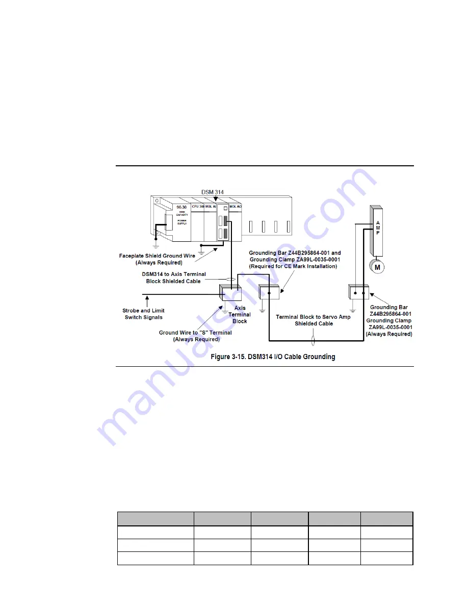
For installations that must meet IEC electrical noise immunity standards, a Cable
Shield Grounding Clamp ZA99L-0035-0001 and one of the 11 available slots on the
Grounding Bar Z44B295864-001 must also be used at the Digital Servo Axis
Terminal Block end of the servo amplifier cable IC800CBL001/002. If the Digital
servo amplifier cable is connected directly to the DSM314 faceplate (no Digital Servo
Axis Terminal Block used) the Grounding Clamp and Bar are not required at the
faceplate end of the cable.
For additional information, refer to Installation Requirements for Conformance to
Standards, GFK-1179.
Figure 45: DSM314 I/O Cable Grounding
I/O Circuit Identifiers and Signal Names
I/O circuit identifiers provide a consistent method of naming the I/O circuits. For example,
IN1 refers to the first of three differential / single ended 5v inputs for each axis.
Signal names are assigned to the circuit identifiers for each axis. The signal name consists of
the circuit identifier followed by a suffix A-D to identify the axis connector. Differential
circuits also have suffixes P (positive) and M (minus) to identify the (+) and (-) signal for each
differential pair.
Example: OUT2 is the circuit identifier for the first differential 5v output on each connector.
The signal names associated with circuit OUT2 are:
Table 21: Signal Names Associated with OUT2
Axis:
Axis 1
Axis 2
Axis 3
Axis 4
Connector:
A
B
C
D
(+) Output Signal:
OUT2P_A
OUT2P_B
OUT2P_C
OUT2P_D
(-) Output Signal:
OUT2M_A
OUT2M_B
OUT2M_C
OUT2M_D