


User Manual
Appendix D
GFK-1742F
Jan 2020
Tuning Digital and Analog Servo Systems
448
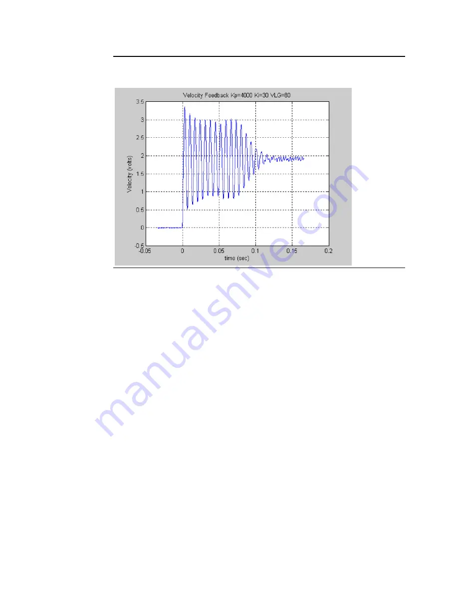
Figure 218: Velocity Loop Step Response Velocity Feedback vs. Time Kp=4000 Ki=30
VLGN = 80
The response shown above represents a marginally stable system. The Velocity Loop Gain is
significantly too large. Notice the significant overshoot and sustained ringing in the
response. This response would not be acceptable.
D-3
System Troubleshooting Hints (Analog Mode)
1.
The DSM314 requires a Series 90-30 CPU with firmware version 10.0 or later, or a
PACSystems RX3i CPU with version 2.8 or later.
2.
The DSM Torque Mode function requires DSM firmware version 3.0 or higher.
3.
If the Drive Ready input is enabled in the module configuration, the input must be
connected to 0v within 1 second after the Drive Enable relay turns on or the Motion
Mate DSM314 will not operate. Incorrect Drive Ready configuration or wiring will
cause Error Code C0h to be reported in the Axis Error Code %AI data.
4.
The ENABLE DRIVE %Q control bit must be set continuously to 1 or no motion other
than Jog moves will be allowed. If no STOP errors (see Appendix A for error codes)
have occurred, the DRIVE ENABLED %I status bit will mirror the state of the ENABLE
DRIVE %Q bit. A STOP error will turn off the DRIVE ENABLED output bit even though
ENABLE DRIVE input bit is still a 1. The error condition must be corrected and the
CLEAR ERROR %Q control bit turned on for one host controller sweep to re-enable
the drive.
5.
If the ERROR %I status bit is 1 and the AXIS ENABLED and DRIVE ENABLED %I status
bits are 0, then a STOP error has occurred (Status LED flashing fast). In this state, the
DSM314 will not respond to any commands other than the CLEAR ERROR %Q control
bit.