


User Manual
Chapter 15
GFK-1742F
Jan 2020
Using the Electronic CAM Feature
359
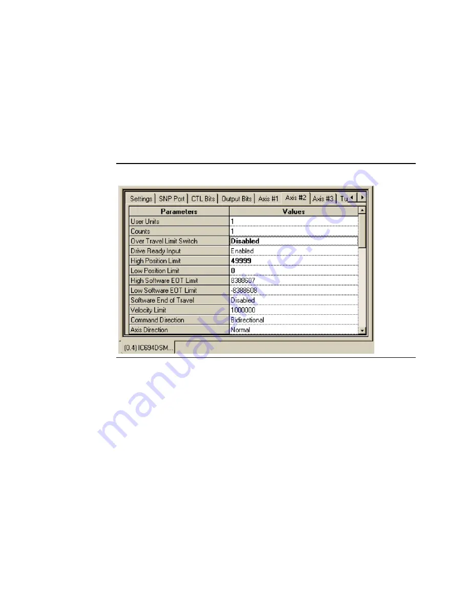
You also need to indicate to Axis #2, the rollover points for the Master axis position
reference. To do this, select the Axis #2 tab in hardware configuration. Input 49,999 into the
High Position Limit and 0 into the Low Position Limit data entry fields. Note that since this is
a Cyclic CAM, the master source high limit, by definition, must be one less than the last point
in the master data table. In this example, this is point 50,000. Thus, the high limit is equal to
49,999. One way to envision this principle is to think of a Cyclic CAM Master as a continuous
circular strip where the first point on the strip is the same as the last point on the strip.
Therefore, in this example, 50,000 is the same point as zero. While in this tab, change the
Home Mode: to Move + and OverTravel Switch to Disabled.
Figure 173: CAM Master Axis Scaling
To finish the configuration, go to the Tuning#1 and Tuning #2 tabs and enter the following
values:
•
Motor Type: 281
•
Position Error Limit: 200 (Optional; see Configuration information for additional
information)
•
In Position Zone: 20 (Optional; see Configuration information for additional
information)
•
Pos Loop Time Const: 200 (Note: Based upon application/mechanics reference
Chapter 4 and Appendix D)
•
Velocity FeedForward: 9000 (Note: Based upon application/mechanics reference
Chapter 4 and Appendix D)
•
Vel Loop Gain: 32 (Note: Based upon inertia attached to motor. Typical demo cases
have a indicator wheel attached that represents approximately this inertia to the
motor