12/112
WL31/WL31TG
The wireless system is suitable for installation in lived-in buildings, for protection for prestigious and artistic
buildings where it is not possible to modify masonry, for installations in areas which can not be reached by the
electric network (e.g. boats, mountain huts, etc), for temporary anti-theft systems.
Two - way radio systems intervals and frequencies are regulated by the CEPT T/R 70-03 European norm but within
Europe each country can autonomously decide whether to comply with this norm and which frequencies to use.
The WL31 radio system uses frequencies which comply with this norm.
Lastly, we would like to remind you what the term “digital signal” refers to. This is a signal in which the transmitted
information is represented by sequences of 0 and 1 values, which is different from an analogical signal where the
transmitted information is represented by a continuously varying physical quantity. This way of transporting
information has many advantages. The main ones are resistance to interferences, ease of signal regeneration,
transmission errors correction and a higher amount of transmittable information. It is exactly for these reasons that
digital signals are superseding analogical signals more and more.
1.4 RADIO SYSTEMS CHARACTERISTICS
Radio systems have specific characteristics which, as far as the practical aspects are concerned, are considerably
different from the systems which use a physical means (e.g. a cable) for transmission. Let’s analyse in detail some
of these characteristics.
The maximum connection distance between two radio devices is set by the strength of the signal which reaches
the receiving device and by the efficiency of the latter in picking it up, which is in “extracting it” from the group of
existing radio-frequencies. Unluckily, many factors can have a negative influence on the received signal strength
and on the receiver’s efficiency. But these causes can be eliminated or reduced with specific actions.
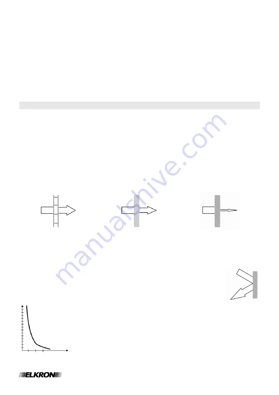
The two main factors which influence the signal’s strength are radio waves absorption and reflection phenomena.
Absorption causes a loss of power to the signal when this must go through specific materials. In this case, the
higher the refraction index, the higher is the absorption caused. The following table shows some of most common
materials grouped according to their refraction index.
Low refraction index
Average refraction index
High refraction index
Wood (e.g. cupboards, furniture),
plastic, synthetic materials (e.g.
Plexiglas), glass, perforated bricks
(e.g. partition walls).
Water (e.g. aquariums), solid bricks,
marble.
Reinforced concrete, bullet proof
glass, metallic structures (desks,
concrete
frames,
domestic
appliances, pipes, gates).
In some cases the signal can be nearly annulled, such as, for example, in metallic cupboards.
Reflection phenomena influence the signal in two ways. The first way is the direction given to the
signal by specific “reflecting surfaces” such as metallic surfaces positioned near the transmitter.
These reflect a considerable amount of the radio waves which hit them. The second way is the
phase displacement of the radio signals, which reaches the receiver after following routes which
are different from the optical one. The sum of out of phase signals can cause a loss of power in
the received radio signal.
Lastly, it is necessary to highlight the fact that the radio signal power decreases
according to the distance squared. In other words, when the distance is doubled, the
power is reduced to a quarter, when the distance is tripled, the power is reduced to a little
more than a tenth.
Power
Distance


