


Pump Removal and Replacement 3–2
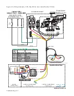
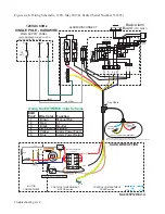
W-Series and Upgrade Stations
1.
Open the alarm panel and shut off all power going to the pump and alarm system.
2.
Remove the station lid.
3.
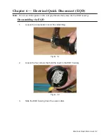
Disconnect the EQD. If the tray cable side of the EQD is wet or shows evidence of
moisture, the EQD insert must be replaced. Determine the source of the moisture
and correct the problem before connecting a new pump to the EQD.
4.
If the unit is equipped with a slide face valve, close the discharge by lifting up on the
handle. Pull the slide face with the discharge hose connected to the pump out of the
discharge assembly; use a long piece of PVC pipe with a 1-inch female threaded
coupling on the end.
If the unit is equipped with a ball valve, close the valve and loosen the compression
nut on the discharge hose.
5.
Use the yellow ropes attached to the pump to pull the pump out of the station; the
pump weighs approximately 120 lbs.
Note:
DO NOT pull the pump out of the station
by the discharge tube, Equalizer tube or power cable.
6.
Lower the new pump into the tank.
7.
Connect the discharge hose to the valve and open the valve.
8.
Perform start-up procedures as described in
Chapter 4 — Start-Up Procedure.
IH Station (Indoor Unit)
1.
Open the alarm panel and shut off all power going to the pump and the alarm
system.
2.
Push the handle down on the inlet pipe gate valve and close the valve.
3.
Close the discharge ball valve.
4.
Loosen the compression nut on the single union ball valve. Take care not to lose the
O-ring; otherwise, the ball valve will hold the pump in place.
5.
Remove the eight bolts that secure the pump to the tank.
6.
Lift the pump out of the tank; the pump weighs approximately 120 lbs.
Note:
DO
NOT pull the pump out of the station by the discharge tube, Equalizer tube or power
cable.
7.
Install the new pump into the tank; use a new gasket.
8.
Secure the pump with the eight bolts.
9.
Connect the single union ball valve. Ensure that the O-ring is in place before
securing the compression nut.
Take care not to over tighten the compression
nut!
10.
Open all valves and perform start-up procedures as described in
Chapter 4 — Start-
Up Procedure.
Содержание Extreme Series
Страница 1: ...Service Manual E One Extreme Grinder Pumps 240V 60 Hz Hardwired Controls...
Страница 2: ......
Страница 32: ...Pump End 5 8 Figure 5 9a D Series Pump Exploded View...
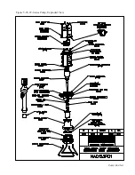
Страница 33: ...Pump End 5 9 Figure 5 9b W Series Pump Exploded View...
Страница 34: ...Pump End 5 10 Figure 5 9c Gatorgrinder GH Series Pump Exploded View...
Страница 35: ...Pump End 5 11 Figure 5 9d IH091 Pump Exploded View...
Страница 36: ...Pump End 5 12...
Страница 58: ...Level Sensor 8 10 Figure 8 35 Level Sensor Assembly Exploded View all hardwired pumps...
Страница 70: ...Mechanical Seal Assembly 11 2...
Страница 75: ......


